


L-LAS-RL Series
Reflected light line sensors| Type | Light source | Working distance | Measur. range | Resolution/ reprodu- cibility | Min. detect. object | Max. scan frequency | LxWxH (mm) | Data sheet |
CAD data |
Appl. | ||
|---|---|---|---|---|---|---|---|---|---|---|---|---|
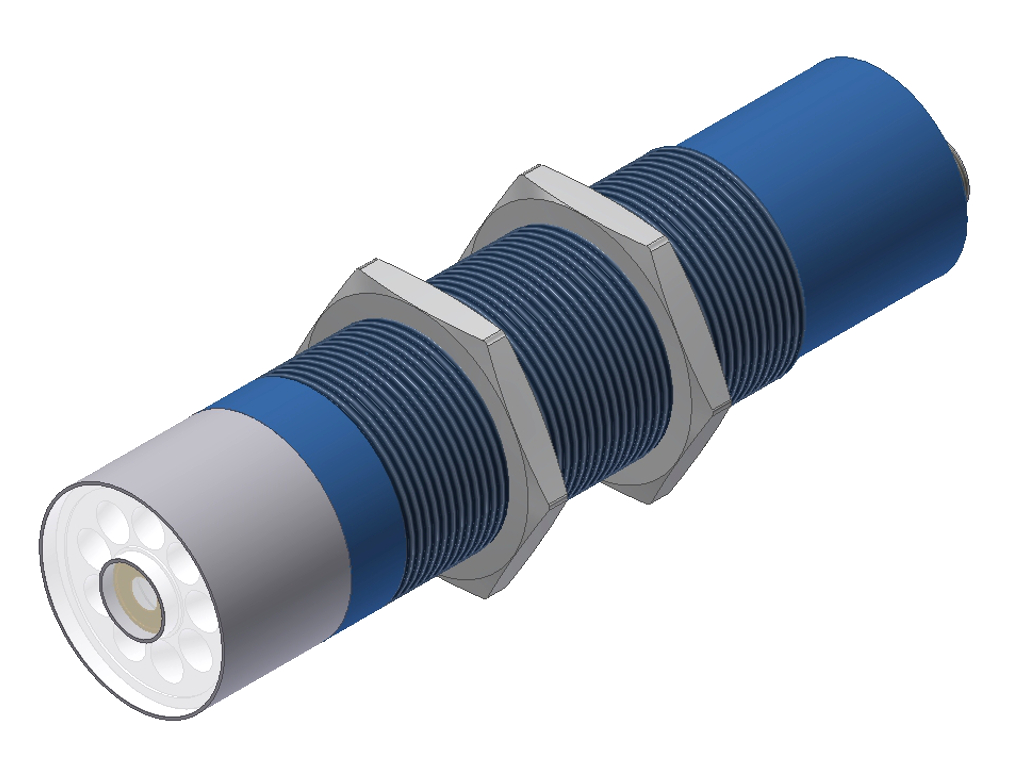
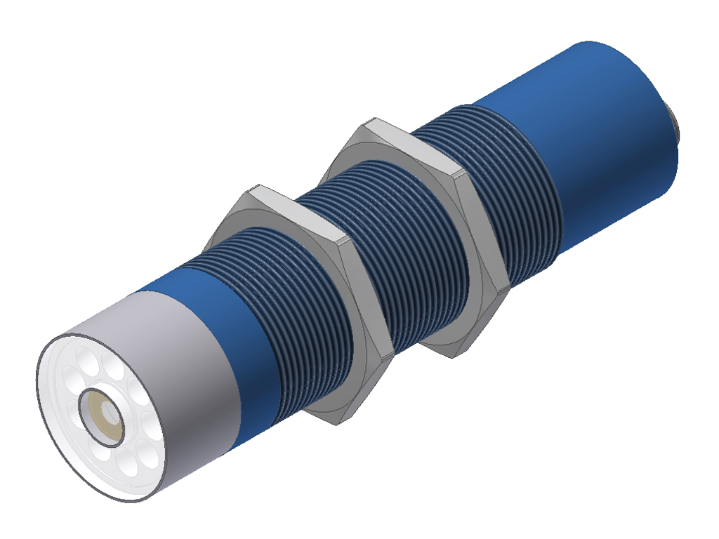
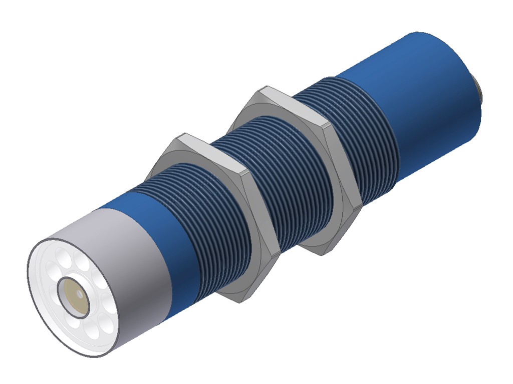
| L-LAS-RL-10-W | 9x white- light LED, diffuse | 33mm ± 3mm | 10mm | 10µm / ± 30µm | 0.05mm | 500Hz | 133xØ34 (M34x1.5) |
|
|
|
|
|
| L-LAS-RL-10-R | 9x red- light LED, diffuse | 33mm ± 3mm | 10mm | 10µm / ± 30µm | 0.05mm | 500Hz | 133xØ34 (M34x1.5) |
|
|
|
|
|
| L-LAS-RL-10-B | 9x blue-light LED, diffuse | 33mm ± 3mm | 10mm | 10µm / ± 30µm | 0.05mm | 500Hz | 133xØ34 (M34x1.5) |
|
|
|
||
| L-LAS-RL-10-UV | 9x UV LED | 33mm ± 3mm | 10mm | 10µm / ± 30µm | 0.05mm | 500Hz | 133xØ34 (M34x1,5) |
|
|
|
||
| L-LAS-RL-20-W | 9x white- light LED, diffuse | 55mm ± 5mm | 20mm | 20µm / ± 60µm | 0.1mm | 500Hz | 133xØ34 (M34x1.5) |
|
|
|
|
|
| L-LAS-RL-20-R | 9x red-light LED, diffuse | 55mm ± 5mm | 20mm | 20µm / ± 60µm | 0.1mm | 500Hz | 133xØ34 (M34x1.5) |
|
|
|
|
|
| L-LAS-RL-20-B | 9x blue-light LED, diffuse | 55mm ± 5mm | 20mm | 20µm / ± 60µm | 0.1mm | 500Hz | 133xØ34 (M34x1.5) |
|
|
|
|
|
| L-LAS-RL-20-UV | 9x UV LED | 55mm ± 5mm | 20mm | 20µm / ± 60µm | 0.1mm | 500Hz | 133xØ34 (M34x1,5) |
|
|
|
|
|
| L-LAS-RL-30-W | 9x white- light LED, diffuse | 75mm ± 5mm | 30mm | 30µm / ± 90µm | 0.15mm | 500Hz | 133xØ34 (M34x1.5) |
|

|
|
||
| L-LAS-RL-30-R | 9x red-light LED, diffuse | 75mm ± 5mm | 30mm | 30µm / ± 90µm | 0.15mm | 500Hz | 133xØ34 (M34x1,5) |
|
|
|||
| L-LAS-RL-30-B | 9x blue-light LED, diffuse | 75mm ± 5mm | 30mm | 30µm / ± 90µm | 0.15mm | 500Hz | 133xØ34 (M34x1.5) |
|
|
|||
| L-LAS-RL-30-UV | 9x UV LED | 75mm ± 5mm | 30mm | 30µm / ± 90µm | 0.15mm | 500Hz | 133xØ34 (M34x1.5) |
|
|
|||
| L-LAS-RL-40-W | 9x white- light LED, diffuse | 100mm ± 10mm | 40mm | 40µm / ± 0.12mm | 0.2mm | 500Hz | 133xØ34 (M34x1.5) |
|
|
|
||
| L-LAS-RL-40-R | 9x red-light LED, diffuse | 100mm ± 10mm | 40mm | 40µm / ± 0.12mm | 0.2mm | 500Hz | 133xØ34 (M34x1.5) |
|
|
|||
| L-LAS-RL-40-B | 9x blue-light LED, diffuse | 100mm ± 10mm | 40mm | 40µm / ± 0.12mm | 0.2mm | 500Hz | 133xØ34 (M34x1,5) |
|
|
|||
| L-LAS-RL-40-UV | 9x UV LED | 100mm ± 10mm | 40mm | 40µm / ± 0.12mm | 0.2mm | 500Hz | 133xØ34 (M34x1.5) |
|
|
GENERAL TECHNICAL DATA:
| Software | Windows® PC software: L-LAS-RL-Scope |
| Variants | ►L-LAS-RL-...-W: White light ►L-LAS-RL-...-R: Red light ►L-LAS-RL-...-B: Blue light ►L-LAS-RL-...-UV: UV light ►L-LAS-RL-...-FE: Split version, frontend with separate electronic control unit, white light |
| Voltage supply | +24VDC (± 10%), reversed polarity protected, overload protected |
| Current consumption | ►with L-LAS-RL-...-W, -R, -B, -UV: <220mA ►with L-LAS-RL-...-FE + L-LAS-RL-CON1: <250mA |
| Max. switching current | 100mA, short-circuit proof |
| Light source | depends on sensor type |
| Line detector | depends on sensor type |
| Measuring range | depends on sensor type |
| Resolution/reproducibility | depends on sensor type |
| Min. detectable object | depends on sensor type |
| Optical filter | depends on sensor type |
| Optical diffusor | ►with L-LAS-RL-...-W, -R, -B, -FE: Surface diffusor screen |
| Analog outputs | Voltage 0...+10V and Strom 4...20mA |
| Digital outputs | ►with L-LAS-RL-...-W, -R, -B, -UV: OUT0, OUT1, OUT2 pnp bright-switching/npn dark-switching or pnp dark-switching/npn bright-switching Output polarity adjustable under Windows® on PC ►with L-LAS-RL-...-FE + L-LAS-RL-CON1: OUT0, OUT1 pnp bright-switching/npn dark-switching or pnp dark-switching/npn bright-switching Output polarity adjustable under Windows® on PC |
| Digital inputs | ►with L-LAS-RL-...-W, -R, -B, -UV: IN0: External trigger Input voltage +Ub/0V, with protective circuit ►with L-LAS-RL-...-FE + L-LAS-RL-CON1: IN0: External trigger IN1: Teach/Reset (double function) Input voltage +Ub/0V, with protective circuit |
| Sensitivity | ►with L-LAS-RL-...-W, -R, -B, -UV: adjustable under Windows® on PC ►with L-LAS-RL-...-FE + L-LAS-RL-CON1: adjustable with tolerance potentiometer or under Windows® on PC |
| Ambient light | bis 3000 Lux |
| Intensity correction | adjustable under Windows® on PC |
| Teach button | ►with L-LAS-RL-...-W, -R, -B, -UV: external teaching via input IN0 (EXT TRIGGER) ►with L-LAS-RL-...-FE + L-LAS-RL-CON1: for norm value teaching or for reset of maximum values via input IN1 (TEACH/RESET) |
| LED display | ►with L-LAS-RL-...-W, -R, -B, -UV (5x LED): LED red (-): Measuring value < lower tolerance threshold LED green: Measuring value within tolerance window LED red (+): Measuring value > upper tolerance threshold (center) LED yellow: Multifunctional LED LED yellow: Power LED ►with L-LAS-RL-...-FE + L-LAS-RL-CON1 (4x LED): LED red (+): Measuring value > upper tolerance threshold LED green: Measuring value within tolerance window LED red (-): Measuring value < lower tolerance threshold LED yellow: Voltage indicator/visualization teach process (multifunctional) |
| Scan frequency | depends on sensor type |
| Interface | RS232, parameterizable under Windows® |
| Housing dimensions | depends on sensor type |
| Housing material | Aluminum, anodized in blue (if optics holding device: anodized in black or nature) |
| Type of connector | ►with L-LAS-RL-...-W, -R, -B, -UV: - to PLC: 8-pole fem. connector Binder 712 - to PC: 4-pole fem. connector Binder 707 ►with L-LAS-RL-CON1: - to PLC: 8-pole fem. connector Binder 712 - to PC: 4-pole fem. connector Binder 707 - to frontend (-FE): 8-pole connector Binder 712 ►with L-LAS-RL-...-FE: - to electronic control unit (-CON1): 8-pole connector Binder 712 |
| Connecting cables | ►with L-LAS-RL-...-W, -R, -B, -UV: - to PLC: cab-las8/SPS - to PC: cab-las4/PC, cab-4/USB or cab-4/ETH ►with L-LAS-RL-...-FE + L-LAS-RL-CON1: - to PLC: cab-las8/SPS - to PC: cab-las4/PC, cab-4/USB or cab-4/ETH - connection frontend to electronic control unit: cab-las8/SPS-fem |
| Operating temp. range | -10°C ... +60°C |
| Storage temp. range | -20°C ... +85°C |
| Enclosure rating | ►with L-LAS-RL-...-W, -R, -B, -UV: Electronics: IP64, optics: IP67 ►with L-LAS-RL-...-FE + L-LAS-RL-CON1: Electronics: IP54, optics: IP67 |
| EMC test acc. to | DIN EN 60947-5-2 |