


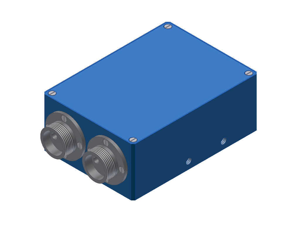
RLS-MD Series
Mark detection sensors| Type | Working distance | Size of light spot | Light source | LxWxH (mm) | Data sheet |
CAD data |
Appl. | ||
|---|---|---|---|---|---|---|---|---|---|
| RLS-MD-2-FIO | 10mm ± 10% | e.g. 6mmx1mm (depends on fiber optics cused) | 2x reflected light fiber optics | 90x65x35 |
|
|
|
|
GENERAL TECHNICAL DATA:
| Software | Windows® PC software: RLS-GD-Scope |
| Voltage supply | +24VDC (± 10%), reversed polarity protected, overload protected |
| Current consumption | <110mA |
| Max. switching current | 100mA, short-circuit proof |
| AC operation | 30kHz |
| Light source | 2 fibres optiques (lumière réfléchie), par exemple R-S-R2.1-(6x1)-1200-67° |
| Working distance | typ. 10mm ± 10% |
| Size of light spot | typ. 6mm x 1mm (by using reflected light fiber optics R-S-R2.1-(6x1)-1200-67°) |
| Ambient light | up to 5000 Lux |
| Interface | RS232, parameterisable under Windows® |
| Switching frequency | max. 5kHz (depends on averaging) |
| Outputs digital (5x) | OUT0...OUT4 (Qinv or Q, adjustable via PC) |
| Outputs analog (2x) | 0...+10V and 4...20mA |
| Input (1x) | IN0 (by means of teach button at the housing) |
| Sensitivity (switching threshold) |
adjustable under Windows® (selection threshold/tolerance window) |
| Pulse lengthening | 0...100ms (adjustable under Windows®) |
| Transmitter power | adjustable under Windows® |
| Averaging | max. 32768 values (adjustable under Windows®) |
| Switching state indicator | by means of 5 yellow LED |
| Housing dimensions | depends on sensor type |
| Housing material | Aluminum, anodized in blue |
| Type of connectors | - to PLC: 8-pole fem. connector Binder 712 - to PLC (optional): 4-pole fem. connector Binder 712 - to PC: 5-pole fem. connector Binder 712 |
| Connecting cables | - to PLC: cab-las8/SPS - to PLC (optional): cab-las4/SPS - to PC: cab-las5/PC, cab-5/USB or cab-5/ETH |
| Operating temp. range | -20°C ... +55°C |
| Storage temp. range | -20°C ... +85°C |
Enclosure rating |
IP54 |
| EMC test acc. to | DIN EN 60947-5-2 |