


Translate this page:
What is edge detection?
An edge generally is a geometrical discontinuity, for example the start of an object or a sudden height increase of an object.
In certain cases the position of an edge must be detected with best possible accuracy, which for example can be done with line sensors (through-beam mode, reflected-light mode – see L-LAS-TB and L-LAS-RL series) or with 2D or 3D camera systems. If, however, edges must be detected at high speed, or edges must be counted, a completely different principle is used that also is excellently suited in case of large distance variations between edge and sensor. Examples for such applications can be found:
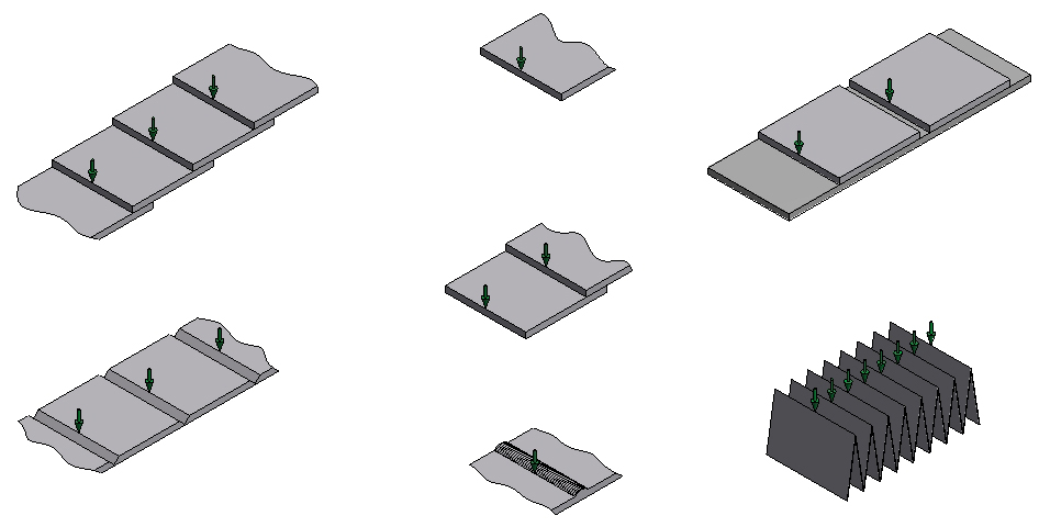
- in the printing industry (sheet counter, copy counter)
- in the metal industry (chatter mark detection, welding seam detection, sheet overlap detection)
- in the packing industry (counting of folded packings)
- in the paper industry (single sheet counting)
- in the plastics industry (film counting and detection)
- in the electrical industry (counting of wires at a winding machine)
- in the automotive industry (edge counting of folded air filter mats)
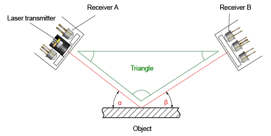
Edge detection according to the triangulation principle
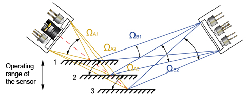
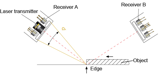
Transmitter, receiver and object are arranged in the form of a triangle. An additional receiver is located at the transmitter side. SI edge detectors us a focused laser diode to ensure a small laser spot at the point of incidence (object). Depending on the properties of the object surface this laser spot is directly or diffusely scattered and also absorbed by the object.
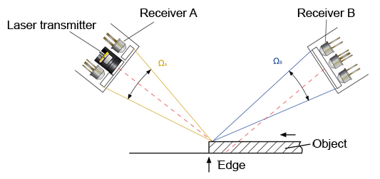
Some of the forward scattered radiation reaches receiver B (solid angle SLB), whereas some of the backward scattered radiation is detected by receiver A (solid angle SLA). Depending on the angle a relatively large operating range can be realised here! Considering the normed value of receiver A (signal A) and receiver B (signal B) the relation is as follows:
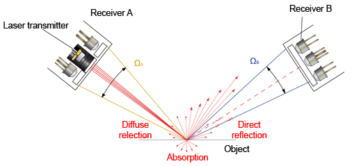
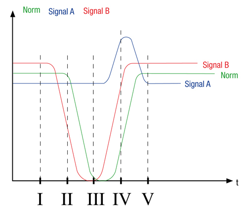
The NORM value is a measurand that in practice is almost independent of brightness fluctuations or color changes of the object surface. So what happens with the NORM value when an edge moves toward the laser spot?
Ι:
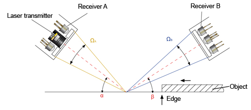
At this time the edge still is so far away from the laser spot that laser light influence zone SLB and SLA are not influenced.

ΙΙ:
The object now already enters the view field of receiver B, the laser light influence zone ΩB becomes smaller, while ΩA remains unchanged. The NORM value therefore also becomes smaller, because SIGNAL B decreases while SIGNAL A remains unchanged.
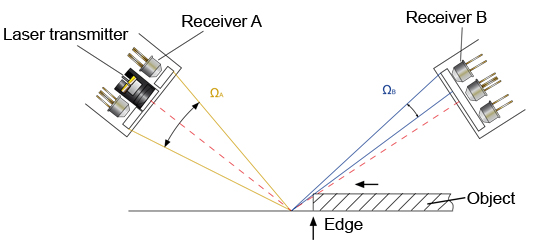
III:
The edge of the object now already covers a considerable part of view field ΩB on the laser spot, the NORM value therefore further decreases! ΩA still remains unchanged.
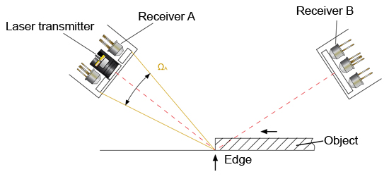
IV:
The edge of the object completely interrupts the visual contact of receiver B to the laser spot. SIGNAL B thus approaches zero, and the NORM value also reaches a minimum!
NORM->Ø!
Signal A of receiver A increases slightly, because due to the object edge initially forward scattered light is scattered back and thus partially reaches receiver A.
V:
The edge of the object now has passed the laser spot, and view contact between laser spot and receiver B is established again. The NORM value reaches almost the same value as under I.
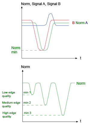
In practice the edges of objects in most cases are not so clearly defined, which is why the NORM value does not reach Ø. The minimum of the NORM value thus is a measure for the "edge quality", i.e. a smaller NORM value means a more clearly defined edge. The edge quality is influenced by the density of the object and by the steepness of the edge.
Since edge detectors mostly are used for the counting of objects, only one signal must be exactly provided for every edge, because otherwise the counting result would be wrong. In addition to reliable edge detection, three additional safety measures have been introduced for this purpose here:
1. Safety measure HYSTERESIS
Edges in practice unfortunately in most cases do not have the ideal step form, an edge rather consists of several edges which in turn may influence the NORM value.
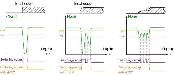
Usually an edge is detected by the sensor's controller when the NORM value falls below a certain threshold THD. When the THD threshold is passed (from high to low) the switching state at the sensor output changes. When the NORM value rises above the threshold again (and there would be no other safety measures), the switching output, as shown in fig. 1a, returns to its initial state.
In figures 1b and 1c the switching threshold is passed several times per edge, which would trigger several pulses.
A second HYST threshold is used to suppress these multiple pulses. The switching process still is triggered by the passing (falling below) of the THD switching threshold. For another pulse to be provided at the output, however, the value must exceed the HYST hysteresis threshold (see fig. 1b, 1c: Switching output with HYST).
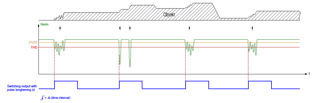
2. Safety measure PULSE LENGTHENING
Another safety measure is to lengthen the switching output after a switching process (falling below the THD threshold) by a certain adjustable time interval (e.g. 1 ms, 2 ms, 5 ms, 10 ms).
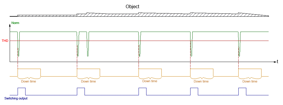
3. Safety measure DEAD TIME
The dead time is the most important safety measure. The term dead time was introduced because the evaluation software more or less is "put to rest" for a certain time, i.e. no evaluation is performed during this time. The dead time is started when the value falls below the THD switching threshold. In ABSOLUTE mode the length of the dead time is defined by the set time period, in RELATIVE mode by the timed sequence of previous edges. A percentage value of the current timed edge distance can be chosen here.
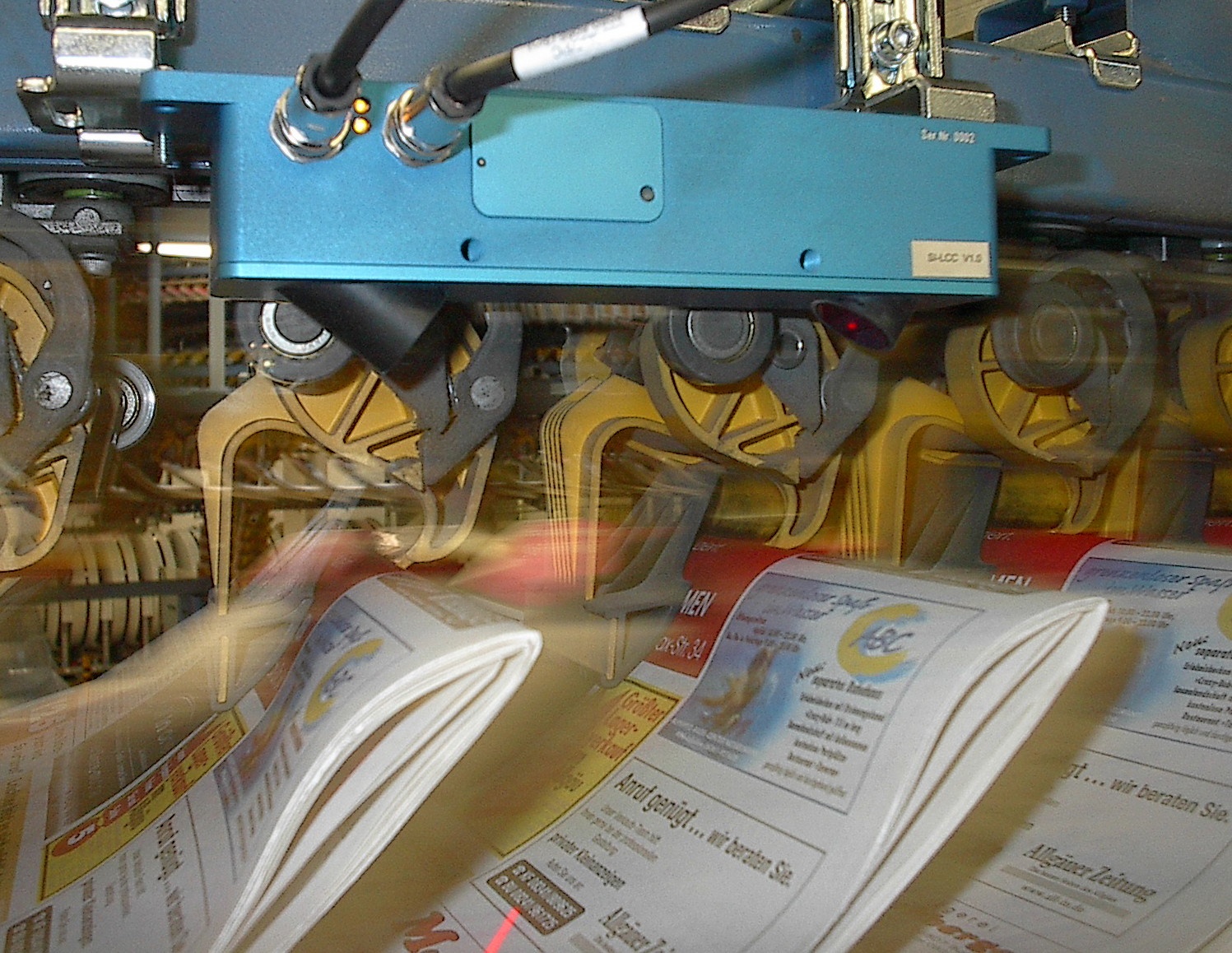
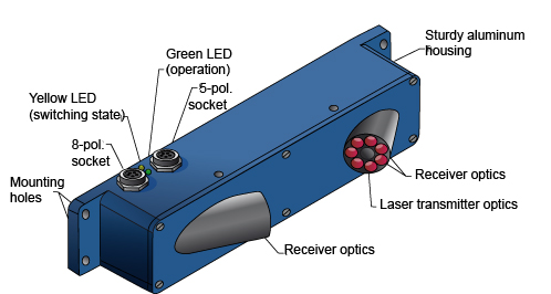
Basic design of an edge detector
Edge detectors of Sensor Instruments are equipped with a modulated laser diode. An optics unit is used to focus the laser light, so that at the object distance there is a laser spot of approx. 20 µm to 100 µ. With the tested laser light and the interference filter at the receiver side this sensor type is extremely insensitive to extraneous light. The edge detectors are parameterised through an RS-232 interface, using a Windows® user interface. This user interface allows easy and optimal settings because the current NORM values (NORM minima) are displayed graphically. The output provides a digital signal that can be directly evaluated, for example by a PLC. The switching process also is visualised by the integrated yellow LED.
Edge detection hardware
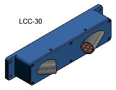
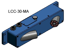
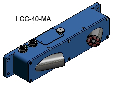
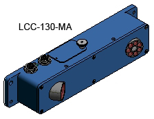
| This type primarily is suited for the counting of high-gloss to dull coloured single sheets in imbricated form (reliable counting e.g. of high-gloss laminate plates). The operating range is 26 mm to 34 mm. The MA version allows the setting of several parameters such as dead time, pulse length, and sensitivity by way of switches that are integrated in the sensor. | 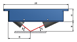 |
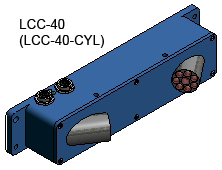
LCC-40, LCC-40-MA and LCC-40-CYL
The LCC-40 and LCC-40-MA types primarily are used for applications with extremely small edges. The sensor for example perfectly detects homogeneous single sheets in imbricated form, starting from a thickness of 40 g/m2, even at high speeds (several m/s). The sensor furthermore is excellently suited for the detection of plastic films (also transparent) in imbricated form. The overlapping position of thin metal colors also can be reliably detected with this type. The sensor has an operating range of 35 mm to 45 mm here. With the MA version the dead time, sensitivity, and pulse length can be set directly at the sensor.
The LCC-40 and LCC-40-MA types primarily are used for applications with extremely small edges. The sensor for example perfectly detects homogeneous single sheets in imbricated form, starting from a thickness of 40 g/m2, even at high speeds (several m/s). The sensor furthermore is excellently suited for the detection of plastic films (also transparent) in imbricated form. The overlapping position of thin metal colors also can be reliably detected with this type. The sensor has an operating range of 35 mm to 45 mm here. With the MA version the dead time, sensitivity, and pulse length can be set directly at the sensor.
| The LCC-40-CYL version features a line-shaped laser light spot (at a distance of 40 mm approx. 3 mm x 0.1 mm). Possible fault positions at the object can thus be better compensated. This type for example also is used for the detection of chatter marks (line-shaped indentations) on bi-metal strips. | 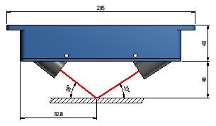 |
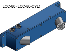
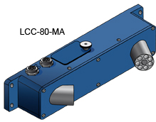
| LCC-80 and LCC-80-MA edge detectors for example are used as copy counters at compensating stackers. These types also are used for welding seam detection at metal sheets or pipes. The operating range of the sensor lies between 60 mm and 100 mm. With the MA type the sensitivity, dead time, and output hold time (pulse length) can be set directly at the sensor with DIP and rotary switches. | 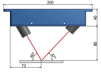 |
| The CYL version has a line-shaped laser light spot that has a size of approx. 3 mm x 0.1 mm at a distance of 80 mm. This allows the compensation of possible production unevenness of the surfaces. | |
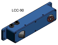
| With its large operating range this sensor type is especially suited for copy counting with a strongly fluctuating distance from the sensor, or for the detection of welding seams on pipes and metal sheets with a strongly varying distance to the sensor. This sensor type also is ideal for counting folded packings. |  |
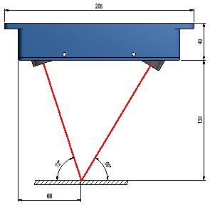
| In combination with two initiators this sensor also is excellently suited for the counting of print copies in overhead conveying applications (in EXTERNAL TRIGGER MODE). With the MA type the sensor can be set (dead time, sensitivity, pulse length) by way of the DIP and rotary switches that are integrated in the housing. The operating range lies between 70 mm and 130 mm. | |

|
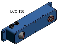
With an operating range of 80 mm to 160 mm this sensor type primarily is used in applications where the product to be counted literally builds up, e.g. in the packing of folded carton boxes. An edge with a thickness of one millimetre must still be reliably detected with a distance variation of up to 80 mm. With the MA type parameters (dead time, pulse length, sensitivity) can be set directly at the sensor.
|
 |
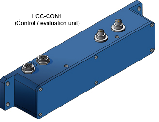
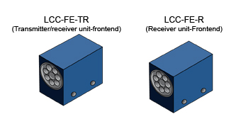
| In this version the actual sensor unit (frontend) is separated from the control unit. These edge detectors can thus be adjusted with outstanding flexibility, because both the distance and the transmitter/receiver angle can be varied here. One frontend in addition features a potentiometer for setting the gain factor, which allows an optimal setting of the NORM value. | 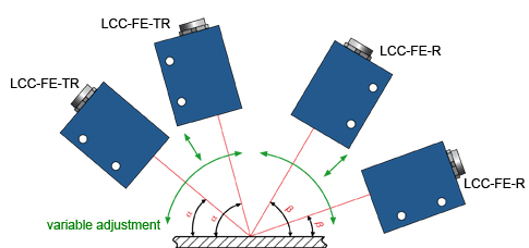 |
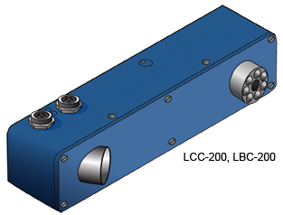
This sensor features a large operating range of 150 mm to 250 mm. It also is available in a version (LBC-200) that in addition to the digital output also has an analog output (0V…+10V). The sensor thus e.g. can be used for the frequency measurement of rotor blades in turbo chargers or fans. The analog signal is proportional to the frequency of the edges (e.g. edges of rotor blades).

Hardware summary
Which type is best suited for what?
|
|
LCC-30 |
|
|
| LCC-40 | |
|
|
| LCC-80 | |
|
|
| LCC-90 | |
|
|
| LCC-130 | |
|
|
| LCC-200, LBL-200 | |
|
|
| LCC-CON1 + LCC-FE-TR + LCC-FE-R | |
|
|
| FIO-80 | |
|
|
Windows® software SI-LCC-Scope V1.0
The PC user interface allows a comfortable parameterisation of the LCC sensors. For this purpose the LCC sensor is connected to the PC by way of the serial interface cable (RS232 bus or USB bus). When parameterisation is finished the edge detector can be disconnected from the PC again.PMOD + POWER [%]: This item is used for setting the laser light power and the laser light power mode. In DYN mode automatic laser light adaptation is activated, and the software determines the optimal light quantity. In FIX mode the laser light power can be entered in the POWER[%] field.
HOLD [ms]: Allows the entering of the output pulse length after an edge is detected.
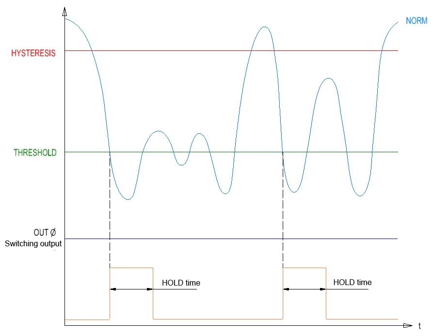
When the NORM value falls below the THRESHOLD value the switching output is activated. At the same time edge detection is deactivated until the HYSTERESIS threshold is exceeded.
THRESHOLD
This input field is used to set the sensitivity of the edge detector. The sensor becomes more insensitive when the threshold is decreased.
This input field is used to set the sensitivity of the edge detector. The sensor becomes more insensitive when the threshold is decreased.
HYSTERESIS
A second threshold is used in order to suppress multiple switching after an edge is detected. The sensor only is activated again when this threshold is exceeded.
A second threshold is used in order to suppress multiple switching after an edge is detected. The sensor only is activated again when this threshold is exceeded.
TRIGGER: ADJ EXT
To make it easier to find a suitable trigger position, a special chart was introduced in the Windows® user software that can be opened under SOURCE: EXT
SOURCE: EXT
This chart shows the current position of the two trigger input signals ING and IN1, as well as the current edge position. INØ lies at Ø and the following ING-Pub at 100. IN1 should approximately lie at 60, the edge approximately in the middle between INØ and IN1, but approximately at 30.
BACKLIM:
This item is used to set an intensity limit. When the value falls below this limit, edge detection is interrupted (DATØ=signal of receiver A, see *edge detection according to the triangulation principle*)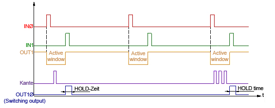
TRIGGER
With TRIGGER=CONT measurement is performed continuously. With TRIGGER=EXT an active window is set by the two digital inputs INØ and IN1, and edge detection only is performed during this active time. If one or several edges are detection during this active period, the switching output is activated without a period defined with HOLD[ms], which avoids multiple counting during a trigger interval (ACTIVE WINDOW)!
REG CNT
This setting value influences the speed of laser power control.
This setting value influences the speed of laser power control.
AVERAGE
This item can be used to average several NORM values.
This item can be used to average several NORM values.
OUTMODE
With DIRECT the switching output after a detected edge changes from LOW (0V) to HIGH (+24V) and after the HOLD time returns to its initial state. With INVERSE the switching output after a detected edge changes from HIGH (+24V) to LOW (0V) and after the HOLD time returns to its initial state.
With DIRECT the switching output after a detected edge changes from LOW (0V) to HIGH (+24V) and after the HOLD time returns to its initial state. With INVERSE the switching output after a detected edge changes from HIGH (+24V) to LOW (0V) and after the HOLD time returns to its initial state.
DT MODE
This item shows the DEAD TIME MODE that is used (see safety measures – DEAD TIME in WHAT IS EDGE DETECTION?). No detection is performed during this dead time. FIX means that a fixed dead time is used. The dead time can be entered in milliseconds under DEAD TIME [ms]. DYN means that a dynamic dead time is used, which can be entered in percent under DEAD TIME [%]. The time between two detected edges is rated as 100%. Depending on the set dead time this percentage value must elapse before edge detection is activated again.
SOURCE
RAW + the receiver signals A (DATØ) and B (DAT1) are visualised on the graphic user interface. The data also are displayed numerically, together with the NORM value.
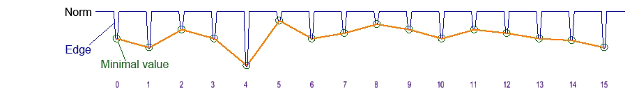
A click on GETBUFF displays the last 16 minimum values of the NORM signal (a minimum-value edge) after a detected edge. The THRESHOLD under which the value must fall also is displayed in the graphic window. After a detected edge the software of the sensor during the DEAD TIME and HOLD TIME starts to search for the smallest NORM value (minimum) and holds this value.
With the help of GETBUFF it is thus possible to optimally set the sensitivity threshold that is required for the respective application, which makes sensor setting much easier.