


Translate this page:
What is distance
measurement & positioning?
|
Reflected-light mode: |
Through-beam mode: |
 |
|
If the measurement frequency is of less importance (<middle) the advantage lies with the L-LAS-TB system, because a higher accuracy can be achieved here due to the high pixel number.
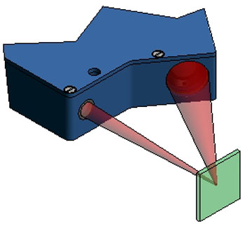
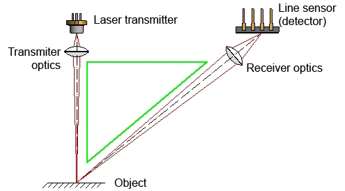
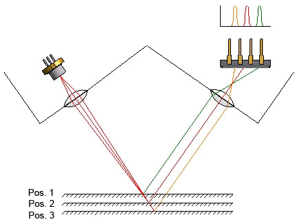
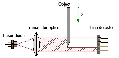
With this measurement principle the light source (laser), the surface to be measured, and the detector are arranged in the form of a triangle.
With a transmitter optics unit the laser spot of the laser diode is projected onto the surface of the object. Through the receiver optics some of the laser light that is scattered from the surface into the half-space reaches the detector line. The line sensors comprises several small photosensors (pixels) that are arranged in a row (depending on the line type 128, 256 512 and 1024 pixels). The signal of those pixels that are hit by the laser light.
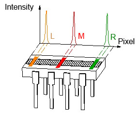
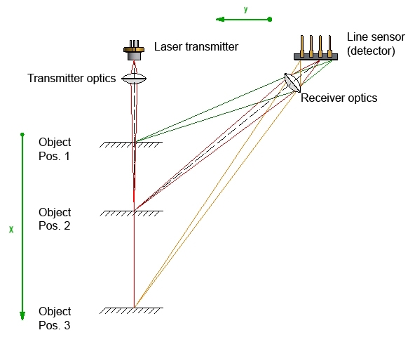
The position of the laser spots on the line detector depends on the position of the objects. A shifting of the object from top to bottom results in a shifting of the projected laser spot from right to left on the detector line (see sketch below):
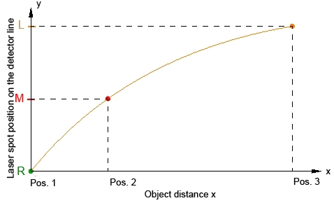
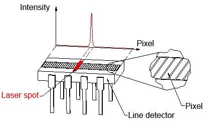
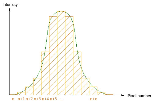
Since as a rule the laser spot simultaneously hits several line pixels, the position can be exactly determined:
.jpg)
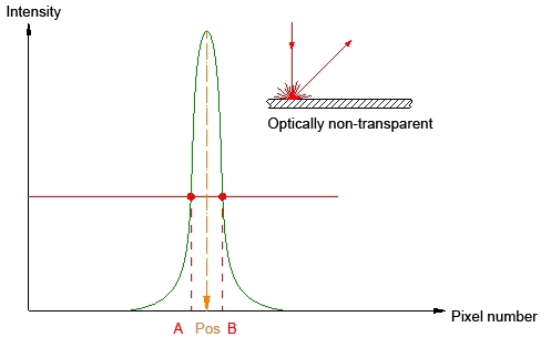
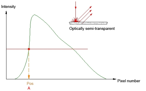
In this measurement care must be taken that the reflected laser beam does not leave the receiver optics, i.e. tilting movements of the object should be minimised.
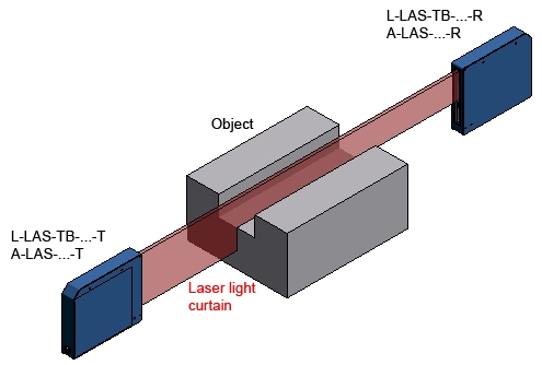
Functional principle of the A-LAS series
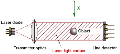
Laser light curtain + receiver optics + photodiode
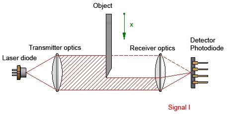
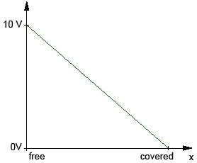
In this through-beam method a part of the parallel laser light curtain is covered by the object. The level of beam covering approximately is proportional to the signal decrease at the receiver. The light arriving at the receiver optics is focused on a detector.
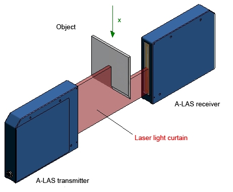
The A-LAS series primarily is used for the distance measurement of fast moving objects. Dirt accumulation compensation is performed during the time when there is no object in the laser light curtain.
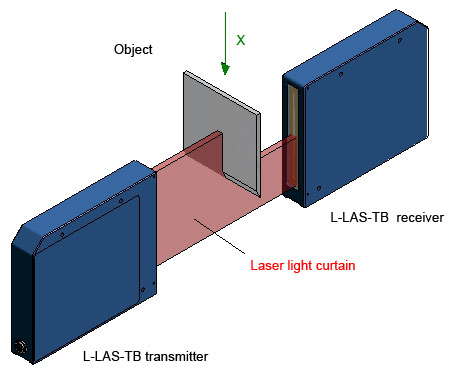
Functional principle of the L-LAS-TB series
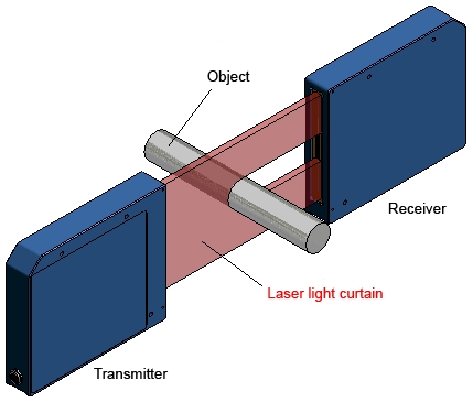
Laser light curtain + line detector
The transmitter unit of the L-LAS-TB series provides a collimated laser light curtain which on the receiver side impinges on a line detector.
When an object is in the laser light curtain, the parallel light guarantees a "sharp" shadow on the detector line.
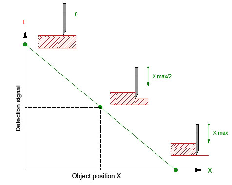
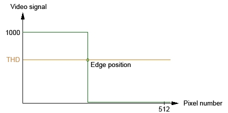
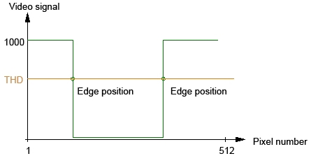
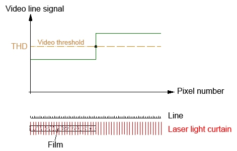
The detector line holds several hundreds of small photosensitive elements that are referred to as pixels (128 pixel, 256 pixel, 512 pixel, 780 pixel, 1024 pixel, 1200 pixel and 1560 pixel). When laser light impinges on the pixels they are illuminated, which results in a signal increase at these pixels. Non-illuminated pixels do not provide a signal. If, however, a pixel is half covered by the object shadow, the signal is at half height.
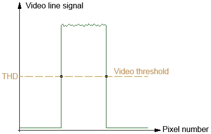
The pixel signal is converted by the A/D converter that is integrated in the sensor processor. The controller in the receiver then compares the video signal of every pixel with a specified adjustable threshold. Pixels at which a crossing of the threshold is determined inform about the position of the "shadow edge" (shadow start or end).
Functional principle of the L-LAS-RL series
Diffuse lighting + line camera in one housing
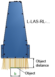
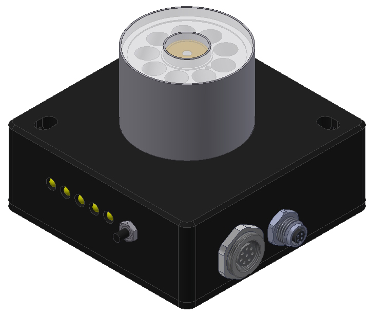
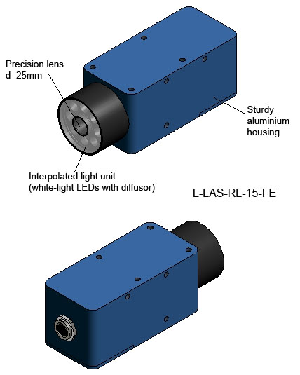
The light source is an array of white-light LEDs, the light of which by means of a diffusor is homogeneously directed onto the measuring surface. A precision lens maps a section of the illuminated surface on a line detector. The video signal that is generated by the line sensor then is evaluated by the controller that is integrated in the sensor housing.
.jpg)
Apart from white-light LEDs, UV LEDs (detection of fluorescent objects) and IR LEDs also are available. UV blocking filters or daylight blocking filters are then used at the receiver side.
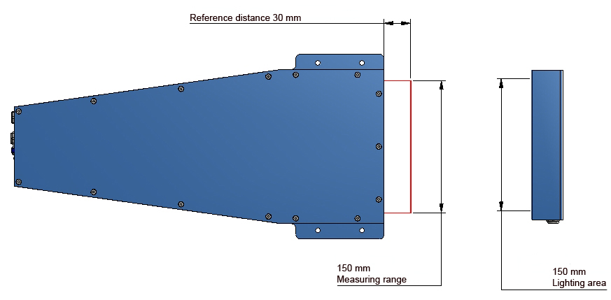
The sensors are available with measurement ranges of 15 mm, 50 mm, 65 mm, 100 mm, 150 mm
and 200 mm.

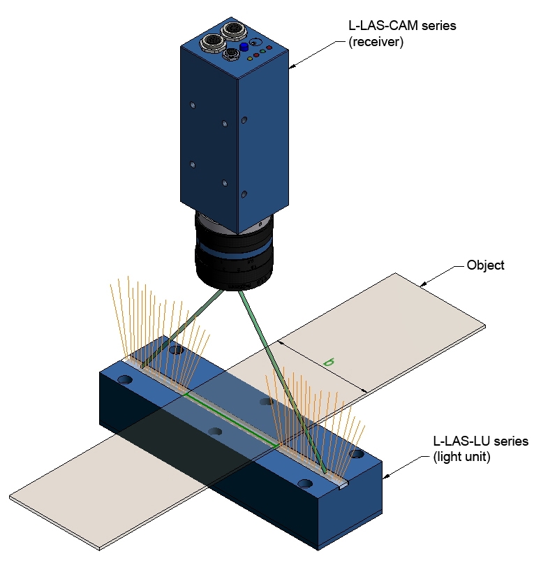
Functional principle of the L-LAS-CAM series
Diffuse lighting + line camera
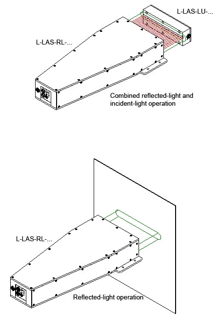
The L-LAS-LU series is available with LED light units of 50 mm to 500 mm in UV, white-light, and IR version. In case of white-light LEDs a diffusor is used in addition to ensure a homogeneous light distribution on the object.
Reflected-light arrangement
.jpg)
Different high-precision measurement lenses incl. various filters and intermediate rings are available for the line cameras (L-LAS-CAM series, focal length from 12.5 mm to 75 mm). Line sensors are available with 256, 512 and 1024 pixels.
Either one or two light units of type L-LAS-LU-… can be used.
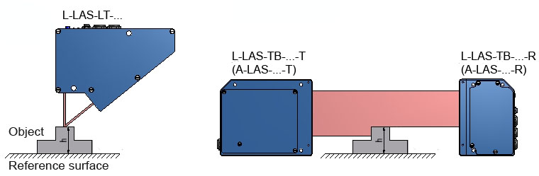
Through-beam arrangement
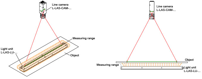
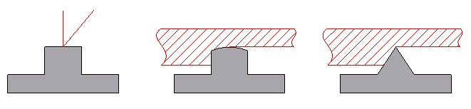
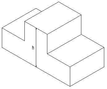
The object rests on a reference surface. Only the upper surface has to be measured.
With certain limitations, depth can be measured both with the through-beam and with the reflected-light method. In the triangulation method care must be taken to ensure that the receiver has a free view field to the laser spot on the measuring surface. When using the L-LAS-TB-… through-beam sensor (A-LAS series) care must be taken to ensure that the laser light curtain can run along the measuring surface. The A-LAS series can be used for fast-moving objects.

The A-LAS series especially is used when objects are moved at high speed.
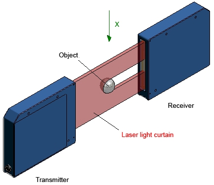
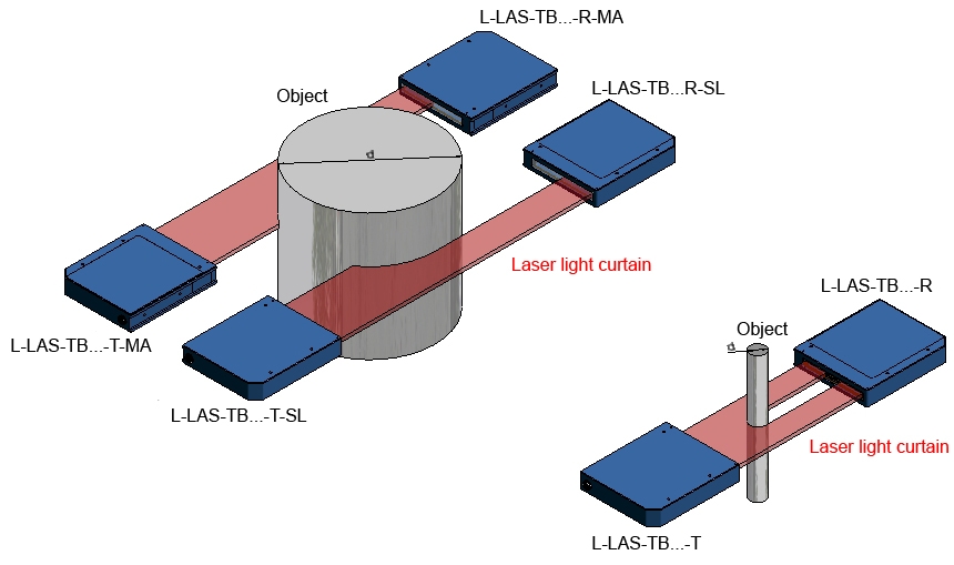
Diameter (diameter measurement)
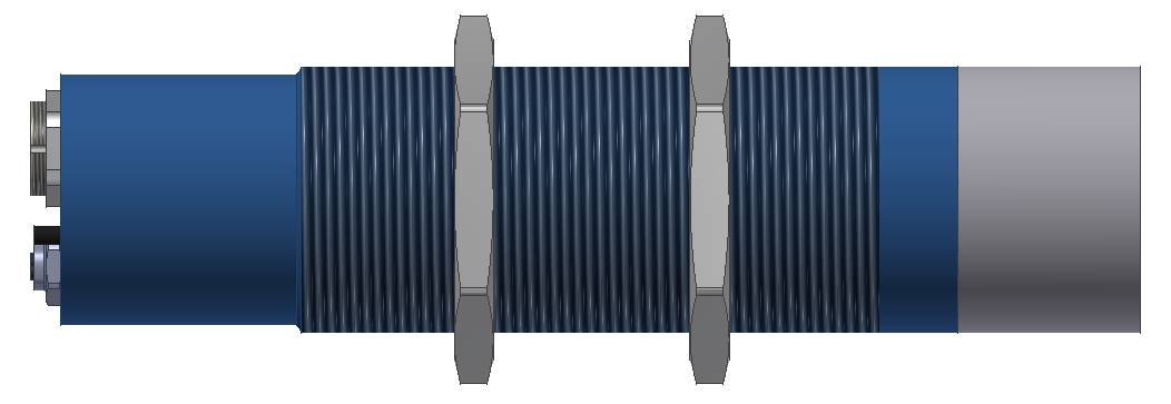
The sensors of the L-LAS-TB series are the best solution for determining the diameter of ball-shaped and cylinder-shaped objects.
Width (width measurement)
.jpg)
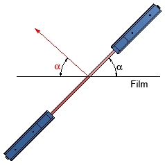
When the sensor unit is arranged at an angle, more light is reflected than in case of vertical arrangement. As a result, and additionally due to absorption by the film, less light arrives at the receiver.
The width measurement of thicker objects also can be performed with a MASTER/SLAVE combination of the L-LAS-LT series.
The width is provided as an analog signal (voltage 0V…10V or current 4 mA - 20 mA) and as a numeric signal on the digital serial bus.
The L-LAS-RL series and the L-LAS-CAM series in combination with the L-LAS-LU series also are suited for the width measurement of film or metal sheets. Special attention must be paid to the object distance from the sensor here, because these sensor systems have a limited depth of focus. The L-LAS-RL series uses the reflected-light mode, whereas the L-LAS-CAM series in combination with the L-LAS-LU series primarily is intended for through-beam operation.


Thickness (thickness measurement)
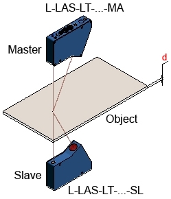
Thickness measurements best can be performed with the L-LAS-LT series in MASTER/SLAVE mode.
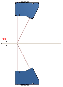

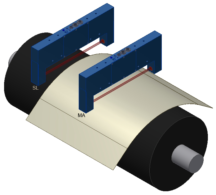
A thickness measurement of film also can be performed with a MASTER/SLAVE combination of L-LAS-TB sensors. The film is pulled over a roll, and a laser through-beam sensor (MASTER) is directed onto the film + roll, while the SLAVE light barrier only is directed onto the roll. The difference between MASTER and SLAVE sensor provides information about the film thickness.

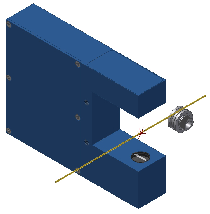
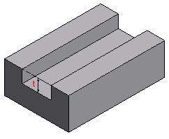
Gap (gap measurement)
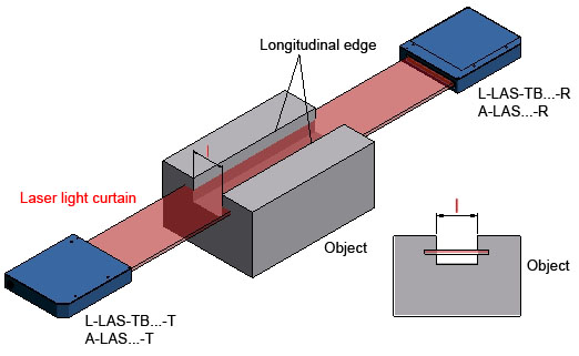
The L-LAS-TB series is suited for gap measurements. Care must be taken to ensure that the optical axis (laser light curtain) is aligned with the longitudinal edge of the object, because otherwise an additional part of the laser light curtain would be covered and the gap would thus appear too small. The A-LAS series primarily is used with very fast moving objects.

Bending (bending measurement)
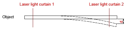
It is recommended to measure against a reference, which can be realised by way of MASTER/SLAVE operation.
.jpg)

Elongation (elongation measurement)
The elongation of an object can be determined with a through-beam system of type L-LAS-TB-… or a reflected-light system of the L-LAS-LT series, each in MASTER/SLAVE arrangement.
.jpg)
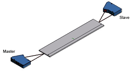
Length (length measurement)
Length measurement with two L-LAS-LT sensors in MASTER/SLAVE arrangement:
.jpg)
Through-beam sensors
Essentially through-beam measurement can be performed with the A-LAS series and the L-LAS-TB series. Both series are available with a separate transmitter and a receiver unit. In the fork version transmitter and receiver unit are contained in the same housing. Due to the telecentric beam path of the transmitter unit measurement can be performed between transmitter and receiver unit almost independently of the measuring position. Through-beam systems of this type have a much higher depth of focus than reflected-light systems.
Advantages
A-LAS series:
- Laser light curtains ranging from 0.5 mm x 0.07 mm up to 100 mm x 5 mm
- Highly compact design
- Analog bandwidth up to typ. 300 kHz
- Scan frequency up to typ. 50 kHz
- Various control units are available
- Economically priced
- Optical fibre version is available (for use in Ex areas), therefore highly compact arrangement
- Very large selection of frontends (fork design or split design)
- Measuring accuracy: typ. 0.2% of aperture size
- Linearity: depending on the aperture size
- Operating distance: max.: 1000 x aperture size (with right aperture: small longitudinal axis)
- Laser light curtains ranging from 8 mm x 2 mm up to 100 mm x 5 mm
- Scan frequency up to typ. 1kHz
- Master/Slave operation
- Several objects can be detected simultaneously
- Measuring accuracy: typ. 0.02% of aperture size
- Linearity: typ. measuring accuracy x 2
- Operating distance: max.: 1000 x laser light curtain width at the transmitter outlet
Reflected-light sensors
- Available with different measuring ranges (25 mm ± 1 mm, 37 mm ± 2 mm, 55 mm ± 5 mm, ... 150 mm ± 1000 mm)
- The laser sensor adapts itself to the respective surface by means of automatic laser power correction
- Scan frequency up to max. 1 kHz
- Available with measuring ranges of 10 mm, 12 mm, 20 mm 30 mm and 40 mm
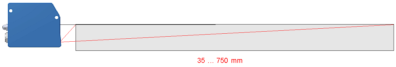
- Operating distances of 35 mm, 50 mm, 75 mm and 125 mm.
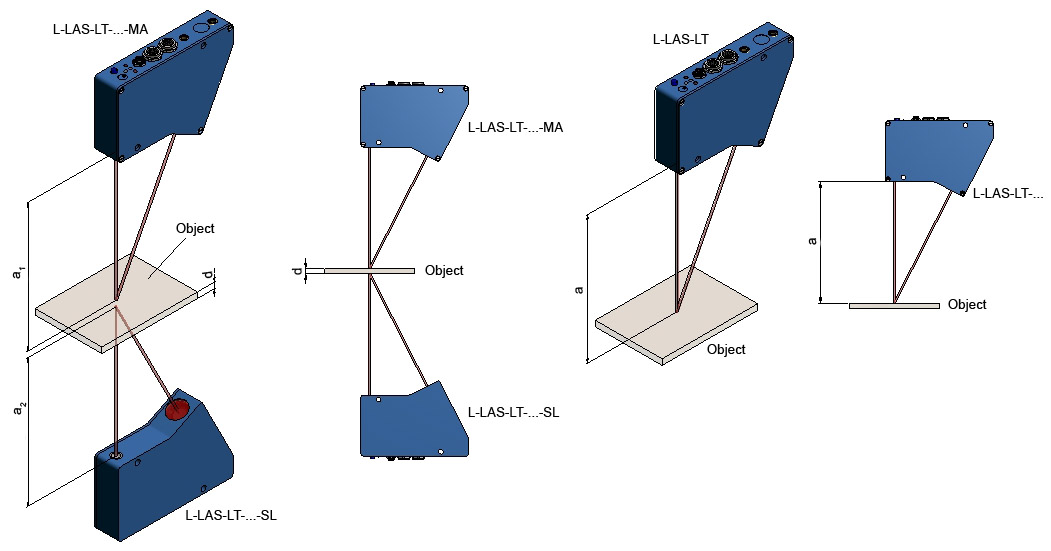
L-LAS-LT-series
The L-LAS-LT series is differentiated into so-called SINGLE types and MASTER/SLAVE systems.
The SINGLE types can be used to measure the distance of an object from the sensor, while the
MASTER/SLAVE systems also can be used to determine the thickness and inclination of objects. The SLAVE sensor in this case supplies the measured distance value to the MASTER sensor. From the two distance values the MASTER sensor then calculates the thickness or inclination of the object.
A-LAS series
Three standard control units are available for the laser analog through-beam light barriers
| SI-CON11 | 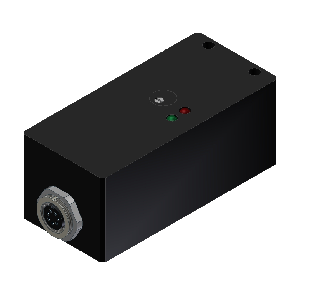 |
| AGL 4 | 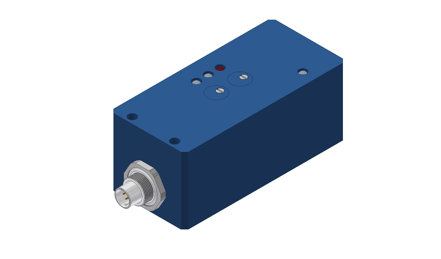 |
| A-LAS-CON1 | 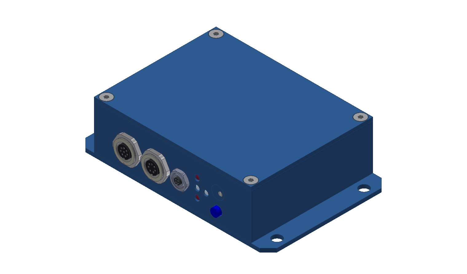 |
| A-LAS-90-T/R |  |
| A-LAS-08-T/R |  |
The most important control units of the A-LAS series
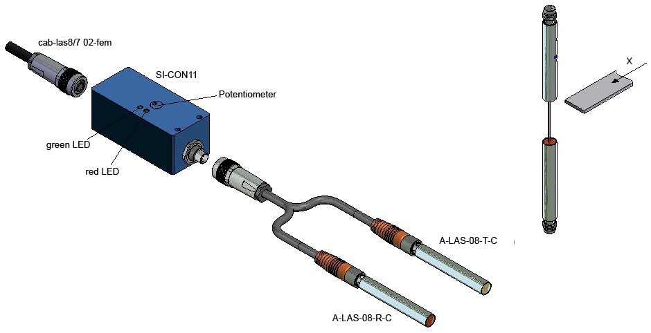
SI-CON11 control unit
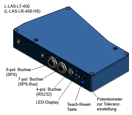
The control unit is connected to e.g. a PLC by means of an 8-pole cable.
The output provides a voltage signal (0V…+10V) and a current signal. Three current variants can be selected here: 0 mA…20 mA, 4 mA…20 mA and 5 mA…25 mA
SI-CON11-4/20
SI-CON11-5/25
The green LED indicates that the amplifier is on, the red LED indicates that the A-LAS sensor is dirty or covered for a longer time. The analog bandwidth is approx. 200 kHz.

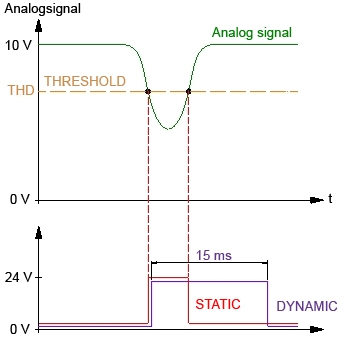
The control unit is connected to a PLC by way of an 8-pole connector. In addition to the analog output
(0V…+10V) the control unit also provides two static digital outputs and two dynamic digital outputs. The analog bandwidth is 100 kHz. The digital outputs have a switching frequency of 25 kHz, in case of the HS version 300 kHz.
With the potentiometer for the gain factor the analog output can be set to 10V (laser light curtain not covered). The second potentiometer is used to set the sensitivity. Automatic threshold correction for the purpose of dirt accumulation compensation can be activated by means of a jumper in the amplifier.
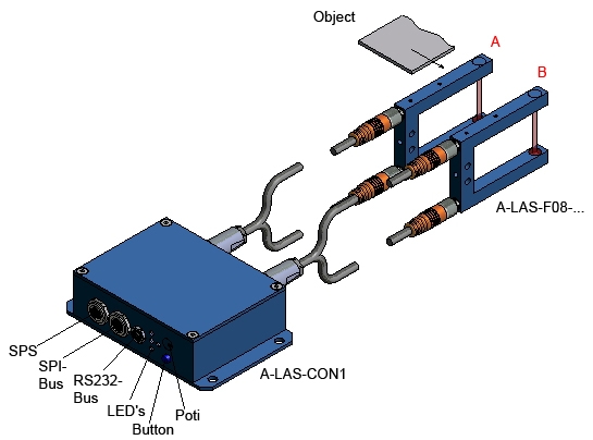
The output switching states are visualised by 4 LEDs at the housing of the A-LAS-CON1 control unit. Two digital inputs allow external triggering for controlling measurement value scanning, and external teaching for setting the tolerance bands. A high-speed 0V – 10V analog output (up to 10 kHz) also is available.
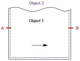
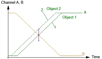
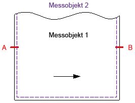
Example - Width measurement with two A-LAS sensors:
Under Windows® the control unit is configured such that channel A is used for measuring, and channel B for triggering. For example, the trigger threshold of channel B can be set to 50%, and at exactly this trigger time channel A is checked for whether the measurement signal lies within the specified tolerances or not. (Object 1 lies within the tolerance, object 2 lies outside the tolerance).
The A-LAS-CON1-FIO control unit also features two sensor input channels, but in this version the laser transmitter and receiver electronics incl. optical filters are integrated in the control unit. The sensor frontends here are through-beam optical fibres of the FIO series (D-…).
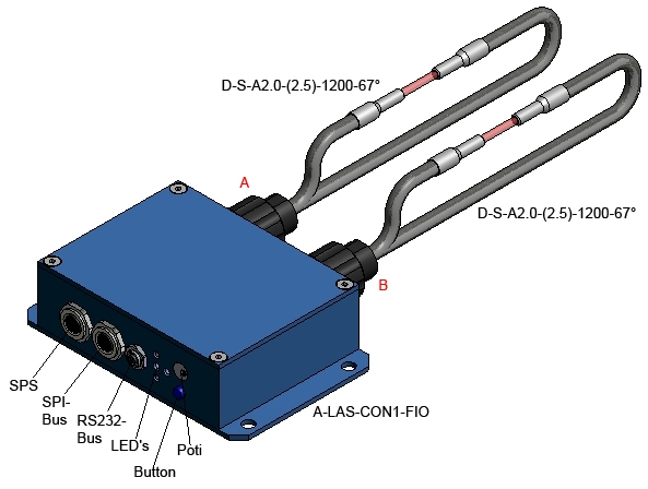
The states of the individual channels can be output by way of three short-circuit-proof, freely configurable digital outputs (OUT 0, OUT 1, OUT 2). Two digital inputs can be used for external triggering and external teaching. An analog output (0V…10V, bandwidth 10 kHz) allows the external monitoring of the sensor signals. When enabled, external teaching can be performed with the integrated potentiometer and button, and the tolerance also can be set with the potentiometer.
The most important A-LAS sensors
Split-type A-LAS sensors
| A-LAS-08-C | 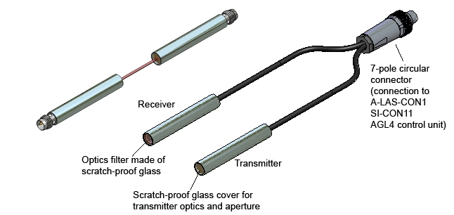 |
| A-LAS-10-C | 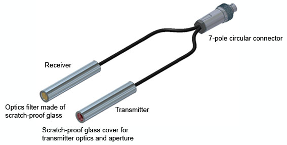 |
| A-LAS-90 | 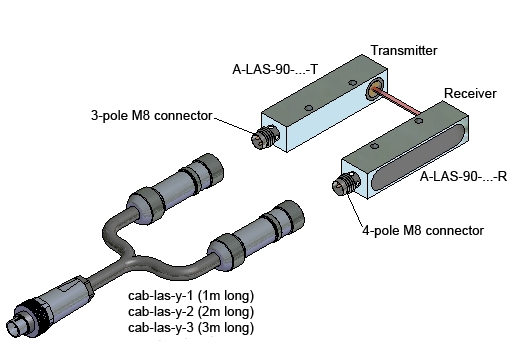 |
| A-LAS-12/90 | 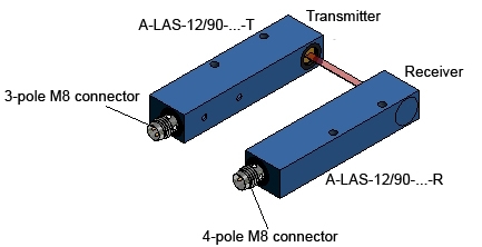 |
| A-LAS-24 | 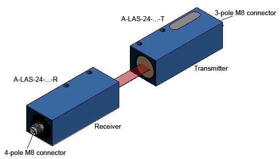 |
| A-LAS-24/90 |  |
| A-LAS-34 | 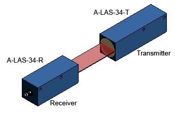 |
| A-LAS-50 | 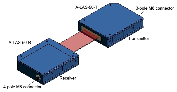 |
| A-LAS-75 | 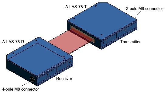 |
| A-LAS-100 | 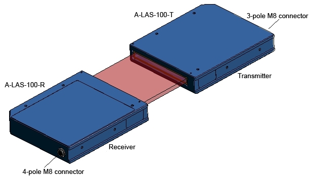 |
Fork-type A-LAS sensors
| A-LAS-F08 | 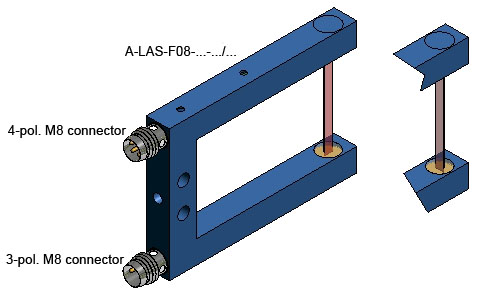 |
| A-LAS-F08-C | 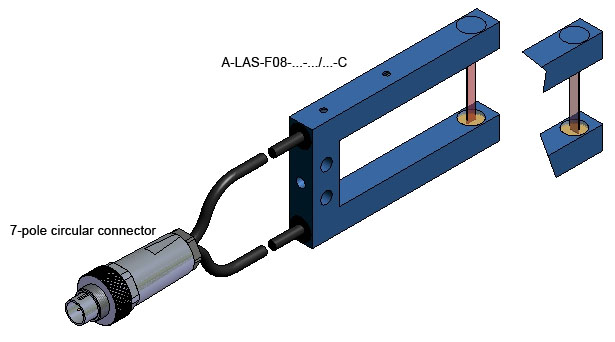 |
| A-LAS-F12 | 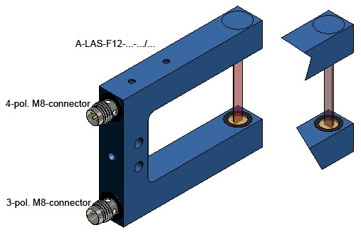 |
| A-LAS-F12-C |  |
| A-LAS-F24 | 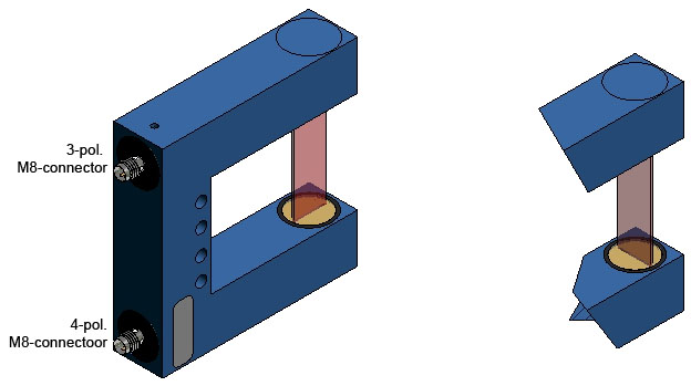 |
L-LAS-TB series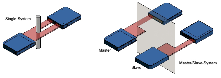
The L-LAS-TB series can be classified into so-called SINGLE systems and MASTER/SLAVE systems.
With SINGLE systems one measuring point can be evaluated, while with MASTER/SLAVE systems 2 measuring points are available. The SLAVE sensor supplies the position data to the MASTER sensor, which in turn calculates the distance value.
| L-LAS-TB-12 | 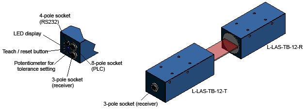 |
| L-LAS-TB-25 | 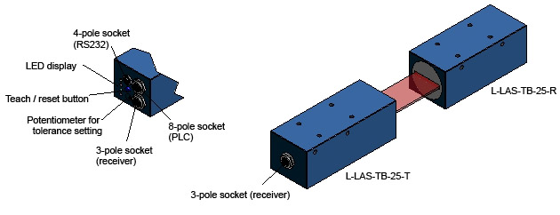 |
| L-LAS-TB-35 | 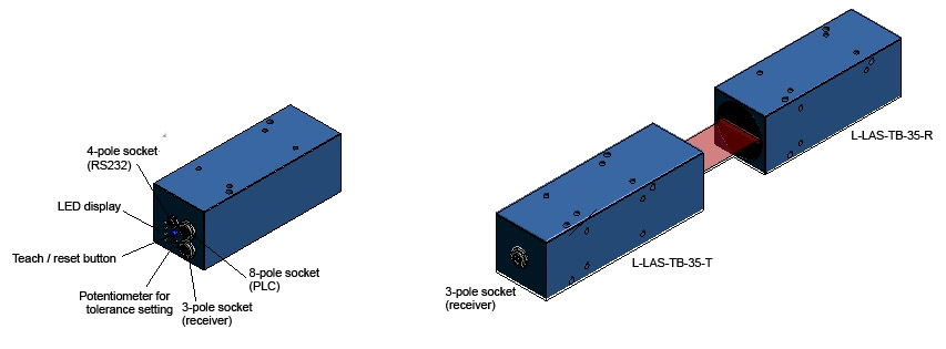 |
| L-LAS-TB-50 | 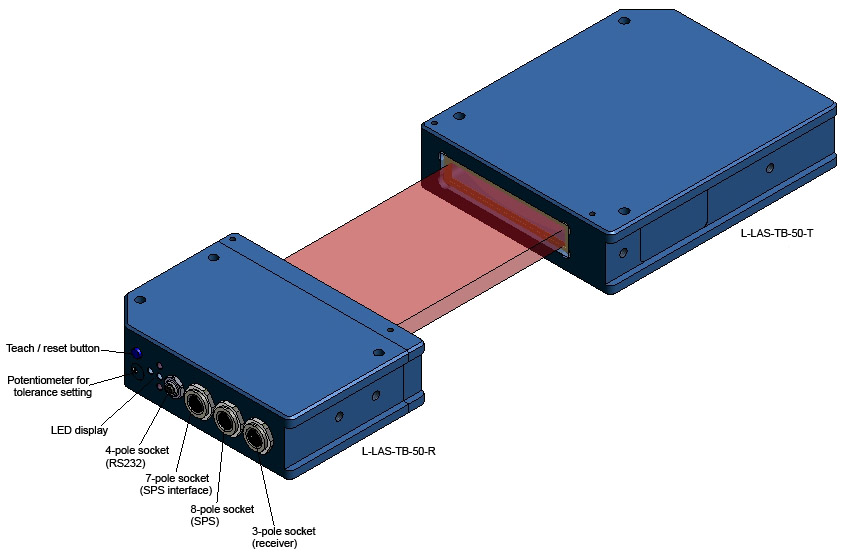 |
| L-LAS-TB-75 | 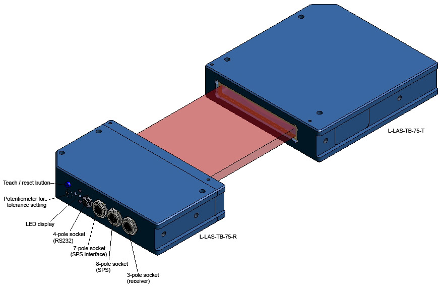 |
| L-LAS-TB-100 | 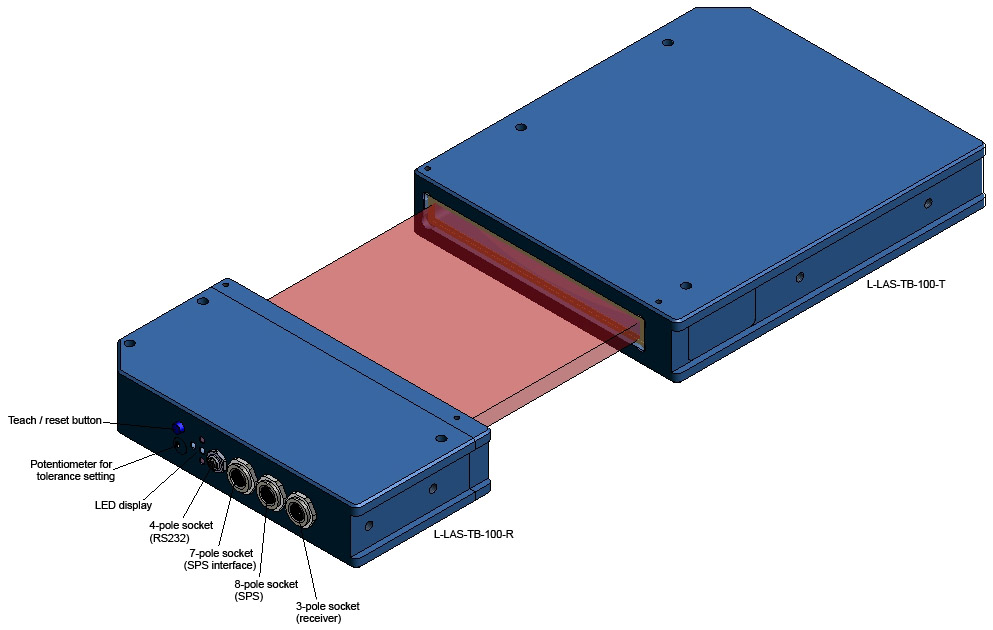 |
Split SINGLE types with separate control unit
| L-LAS-TB-8 | 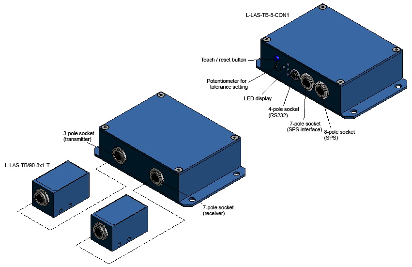 |
| L-LAS-TB-6 (control unit + frontend) |
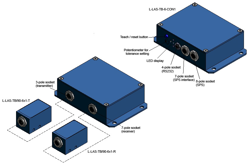 |
| L-LAS-TB-12 (control unit + frontend) |
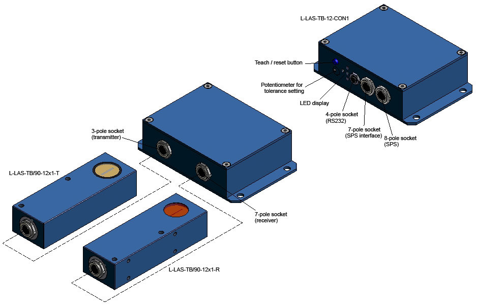 |
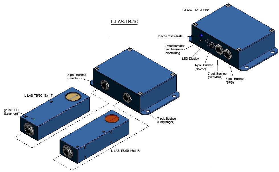
| L-LAS-TB-16 (control unit + frontend) |
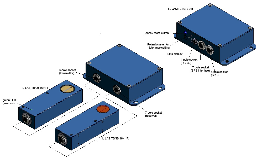 |
| L-LAS-TB-F-8x1-40/40 and L-LAS-TB-F-1x8-40/40 |
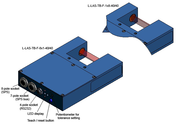 |
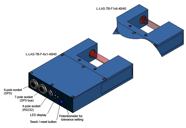
| L-LAS-TB-F-6x1-40/40 and L-LAS-TB-F-1x6-40/40 |
 |
| L-LAS-TB-F-6x1-100x100 and L-LAS-TB-F-1x6-100x100 |
|
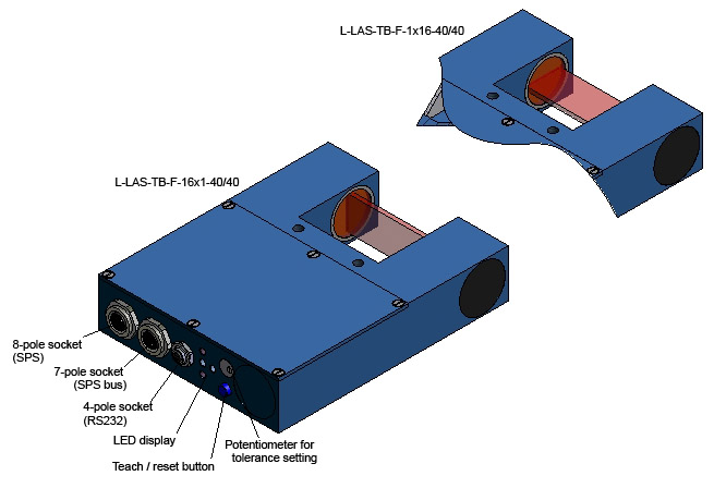
| L-LAS-TB-F-16x1-40/40 and L-LAS-TB-F-1x16-40/40 |
 |
| L-LAS-TB-F-8x1-200/40 and L-LAS-TB-F-1x8-200/40 |
 |
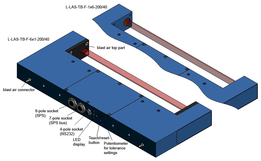
| L-LAS-TB-F-6x1-200/40 and L-LAS-TB-F-1x6-200/40 |
 |
| L-LAS-TB-F-16x1-200/40 and L-LAS-TB-F-1x16-200/40 |
 |
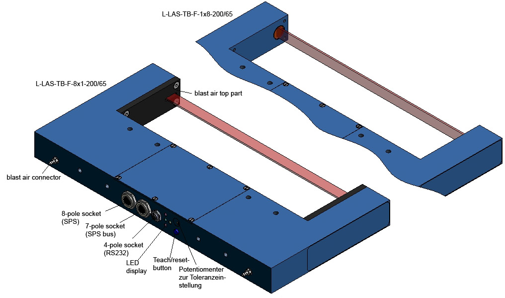
| L-LAS-TB-F-8x1-200/60 and L-LAS-TB-F-1x8-200/65 |
 |
| L-LAS-TB-F-6x1-200/65 and L-LAS-TB-F-1x6-200/65 |
 |
| L-LAS-TB-F-16x1-200/65 and L-LAS-TB-F-1x16-200/65 |
 |
| L-LAS-TB-6-CL | 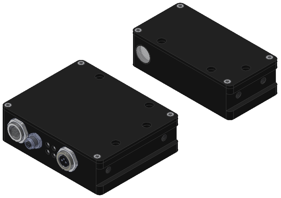 |
| L-LAS-TB-14-CL | 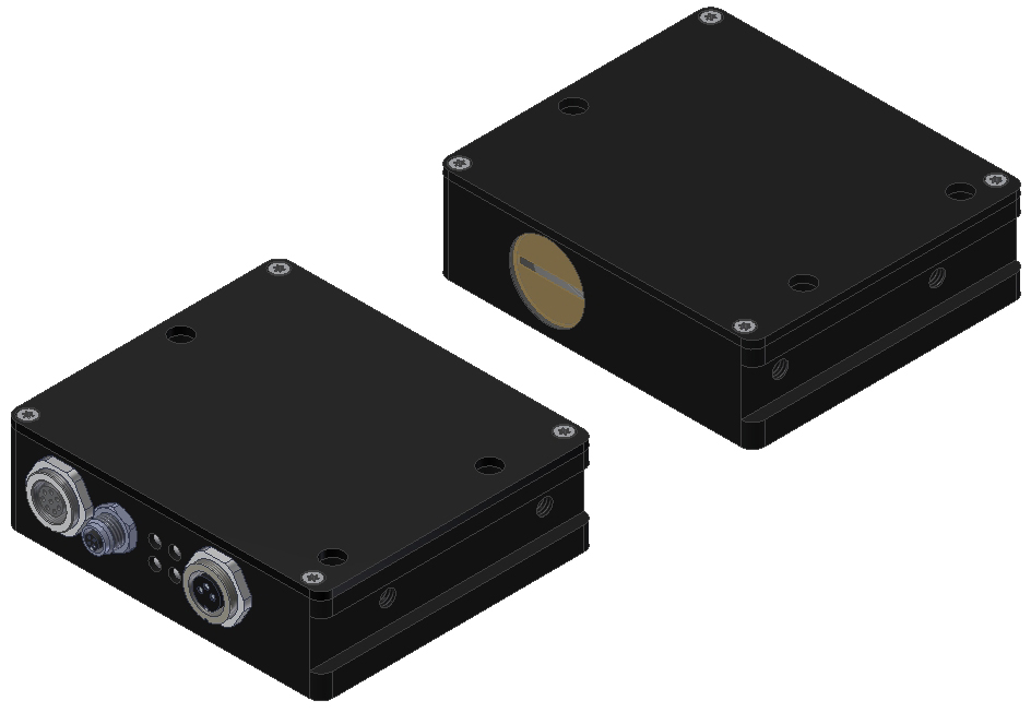 |
| L-LAS-TB-16-CL | 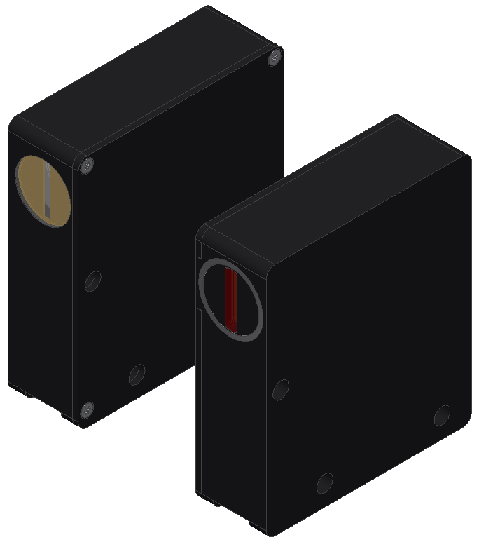 |
| L-LAS-TB-28-CL | 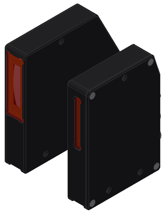 |
| L-LAS-TB-50-CL | 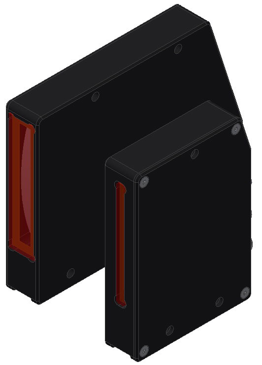 |
| L-LAS-TB-75-CL |
 |
| L-LAS-TB-100-CL | 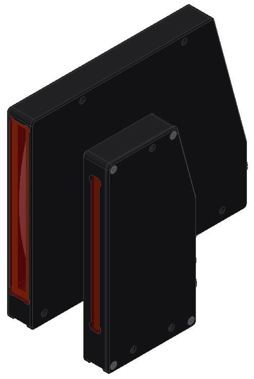 |
| L-LAS-TB-F-16x1-100/100-CL | 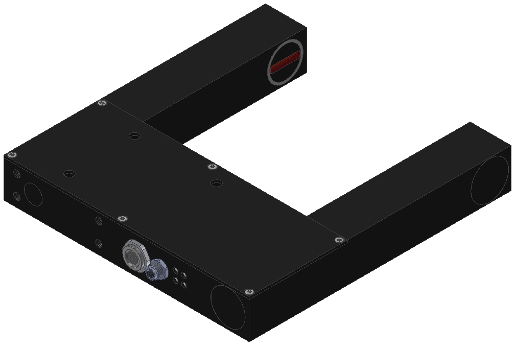 |
| L-LAS-TB-F-6x1-40/40-CL | 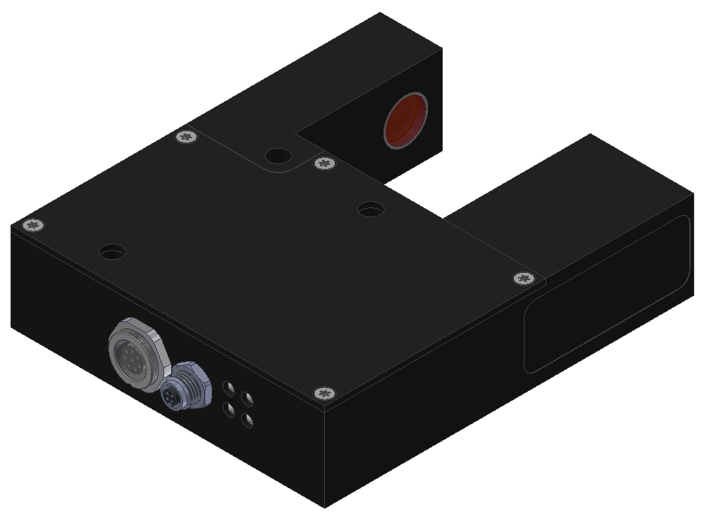 |
| L-LAS-TB-F-6x1-20/40-CL | 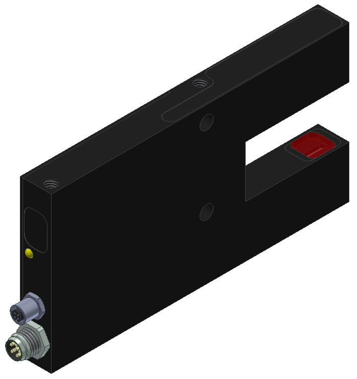 |
| L-LAS-TB-F-6x1-100/100-CL | |
| L-LAS-TB-F-16x1-40/40-CL | .jpg) |
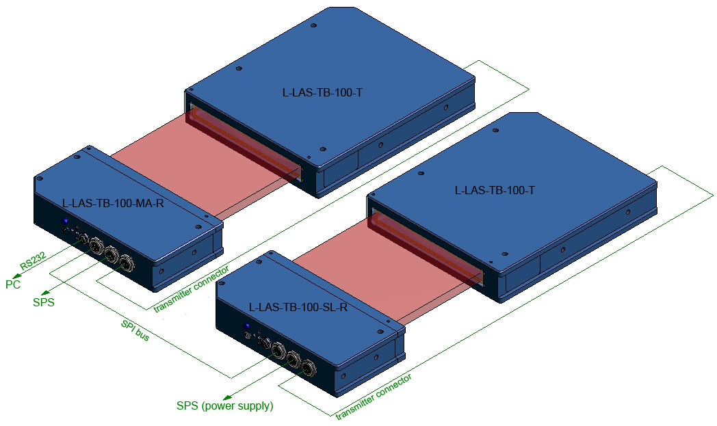
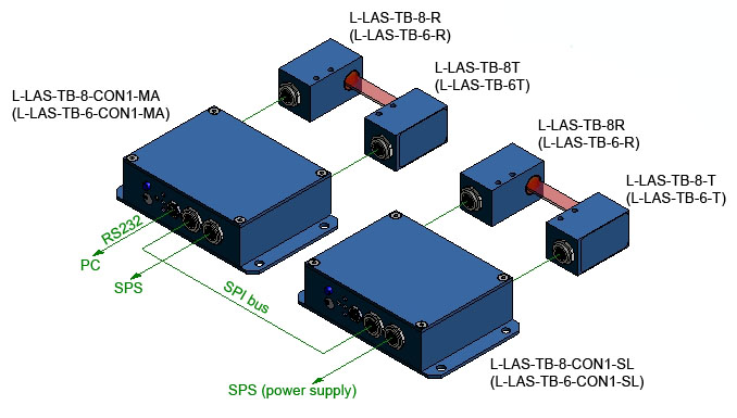
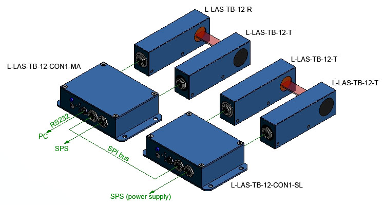
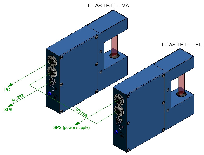
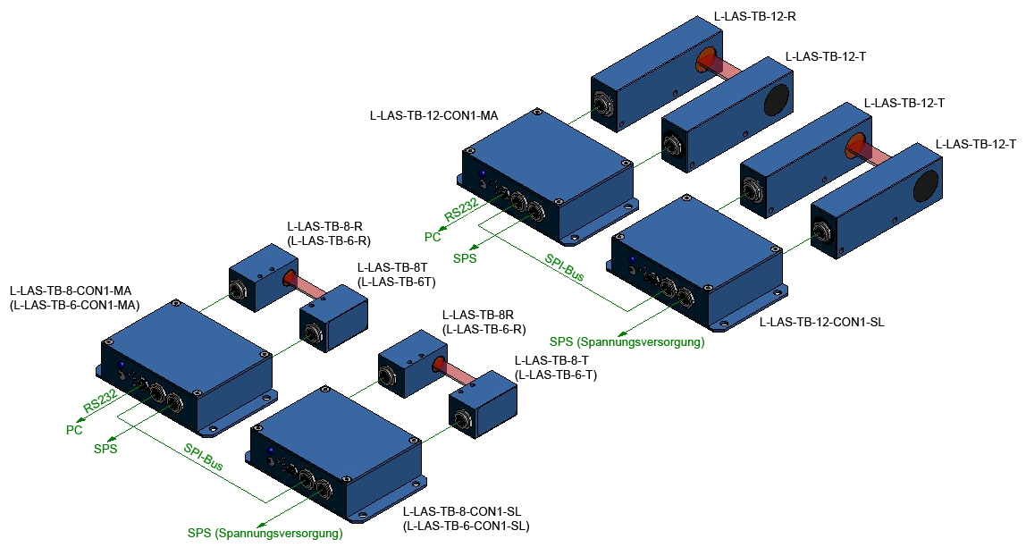
MASTER/SLAVE types
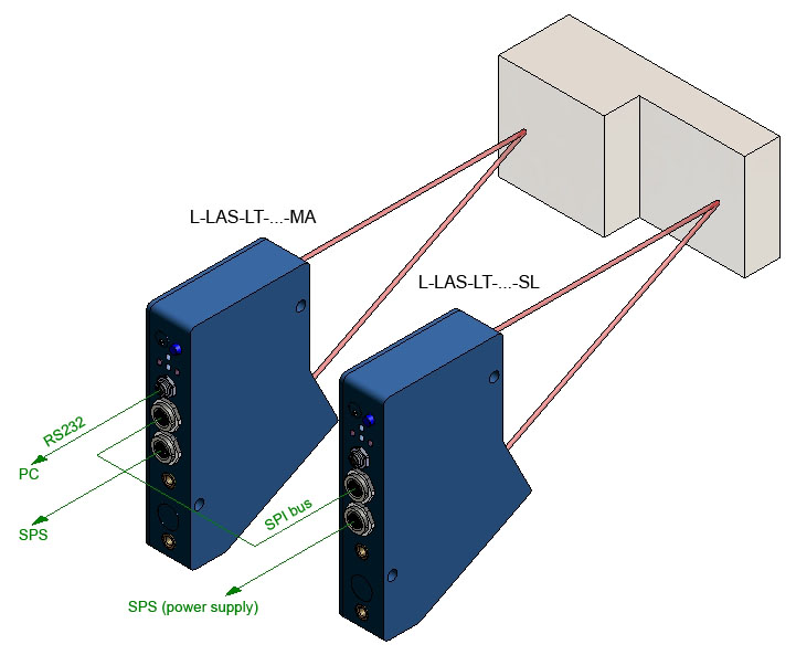
Data exchange between MASTER and SLAVE sensors is effected through the SPI bus (digital-serial bus).
At each sensor the SPI bus is provided by way of a 7-pole circular socket. The two sensors are connected by means of the cab-las-7-male connecting cable that is available in different lengths (1 m, 2 m, 3 m and 0.5 m).
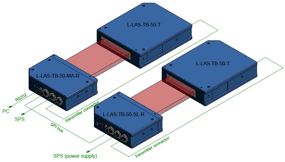
The technical data are the same as of the SINGLE systems, only the software and part of the interface electronics are slightly different.

| L-LAS-TB-F-16x1-100/60-MA and L-LAS-TB-F-16x1-100/60-SL |
-100_60_MS.jpg) |
| L-LAS-TB-F-6x1-200/40-MA and L-LAS-TB-F-6x1-200/40-SL |
-200_40_MS.jpg) |
| L-LAS-TB-F-8x1-200/40-MA and L-LAS-TB-F-8x1-200/40-SL |
-200_40_MS.jpg) |
Reflected-light sensors
The SINGLE types can be used to measure the distance of an object from the sensor, whereas with the MASTER/SLAVE systems the thickness and inclination of objects also can be determined. The SLAVE sensor supplies the measured distance value to the MASTER sensor, which then calculates the thickness or inclination of the object from the two distance values.
SINGLE types
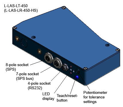
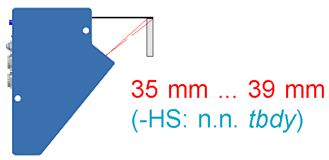
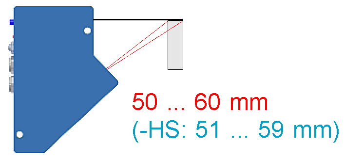
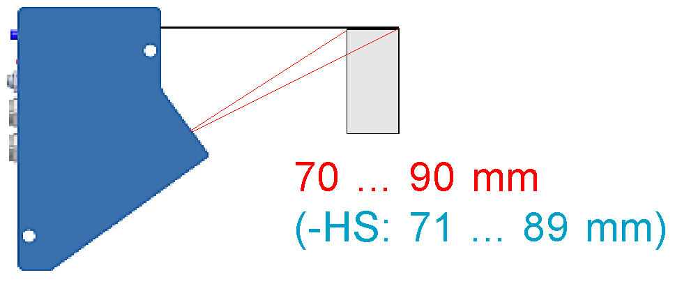
L-LAS-LT-450 and L-LAS-LT-450-HS
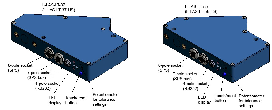
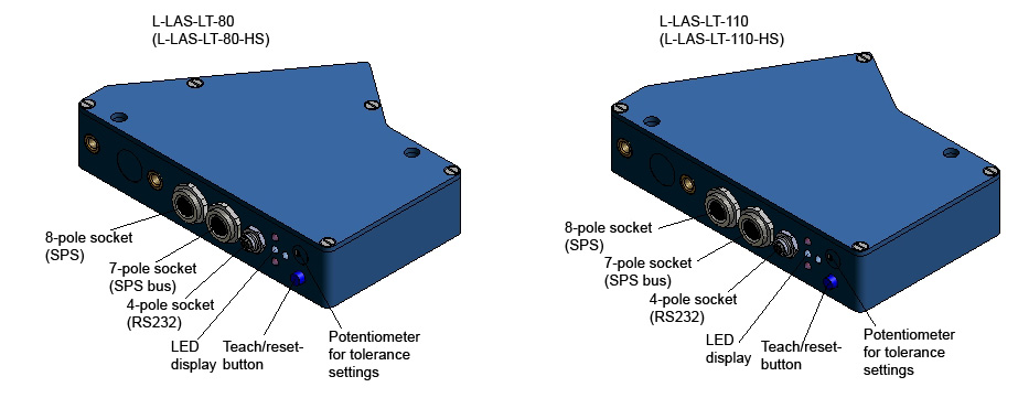
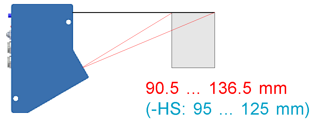
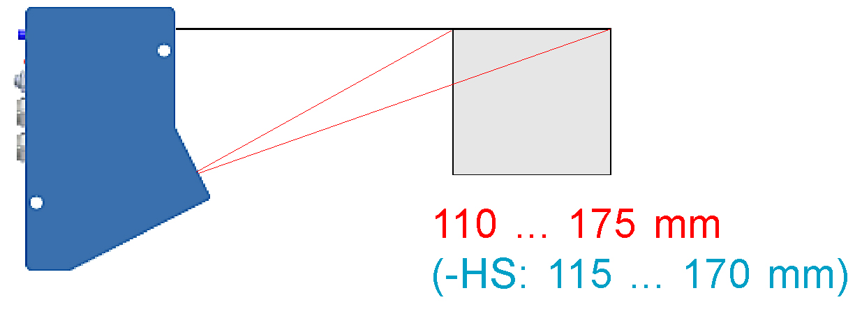
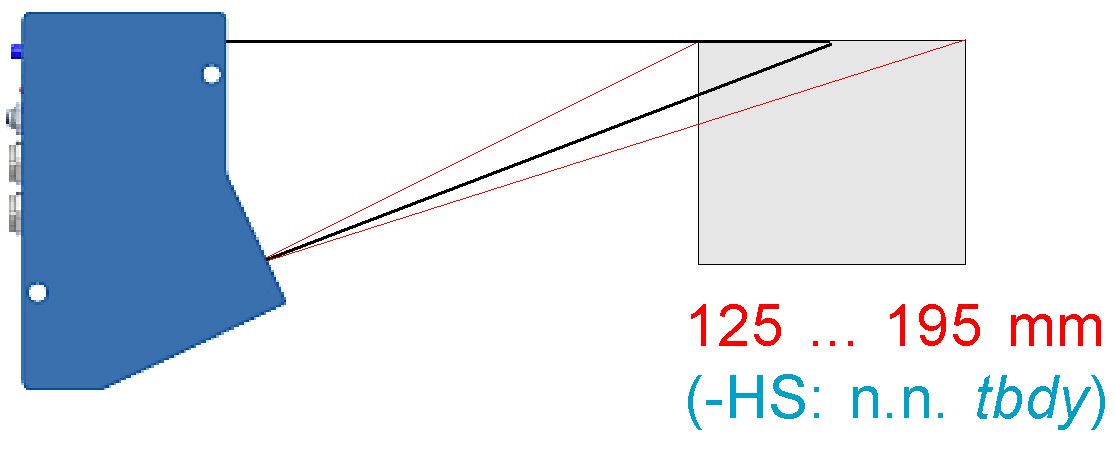
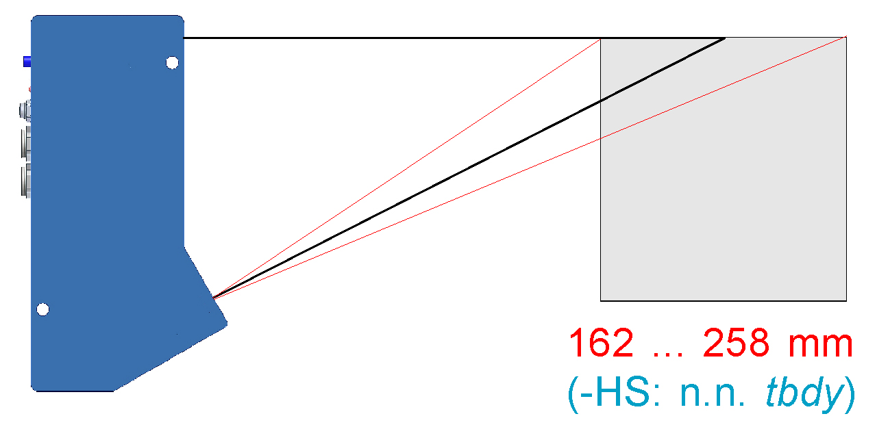
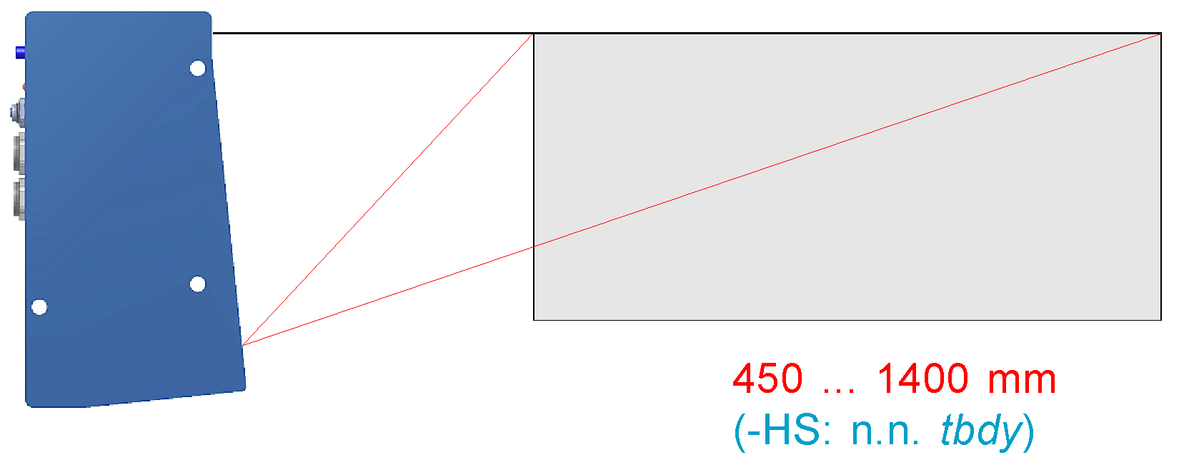
Measuring ranges L-LAS-LT-... (single)
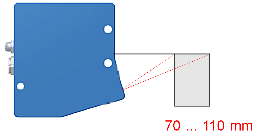
L-LAS-LT-37 L-LAS-LT-37-HS L-LAS-LT-37-RA L-LAS-LT-37-RA-HS |
 |
| L-LAS-LT-55 L-LAS-LT-55-HS L-LAS-LT-55-RA L-LAS-LT-55-RA-HS |
 |
| L-LAS-LT-80 L-LAS-LT-80-HS L-LAS-LT-80-RA L-LAS-LT-80-RA-HS |
 |
| L-LAS-LT-110 L-LAS-LT-110-HS L-LAS-LT-110-RA L-LAS-LT-110-RA-HS |
 |
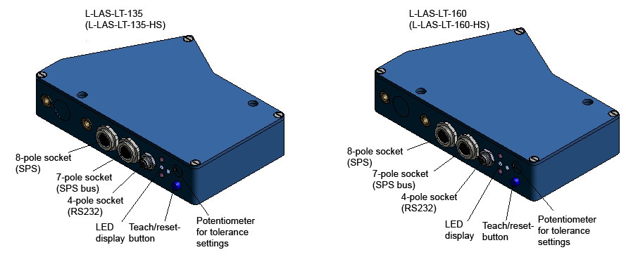
| L-LAS-LT-135 L-LAS-LT-135-HS |
 |
| L-LAS-LT-160 L-LAS-LT-160-HS |
 |
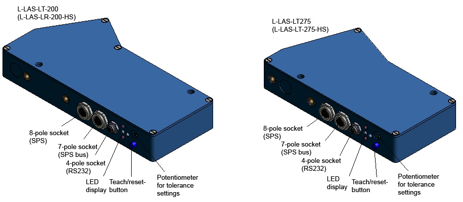
| L-LAS-LT-200 L-LAS-LT-200-HS |
 |
| L-LAS-LT-275 L-LAS-LT-275-HS |
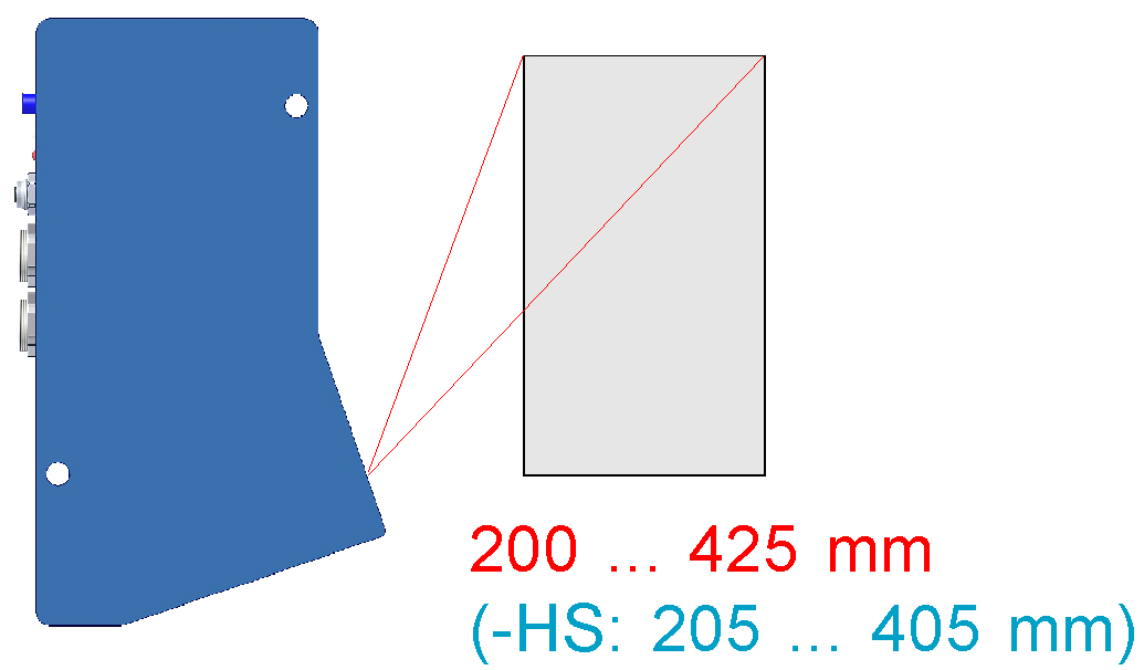 |
| L-LAS-LT-450 L-LAS-LT-450-HS |
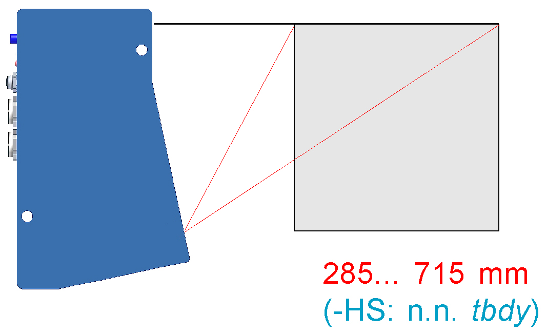 |
| L-LAS-LT-1000 L-LAS-LT-1000-HS |
 |
L-LAS-LT-…-CL Compact Line (single)
| L-LAS-LT-20-CL |  |
| L-LAS-LT-38-CL | .jpg) |
| L-LAS-LT-50-CL |  |
| L-LAS-LT-120-CL |  |
| L-LAS-LT-165-CL |  |
| L-LAS-LT-250-CL |  |
| L-LAS-LT-157-CL |  |
| L-LAS-LT-85-RA-CL |  |
Measuring ranges L-LAS-LT-...-CL (Single)
| L-LAS-LT-20-CL |  |
| L-LAS-LT-38-CL | 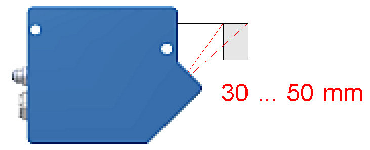 |
| L-LAS-LT-50-CL | 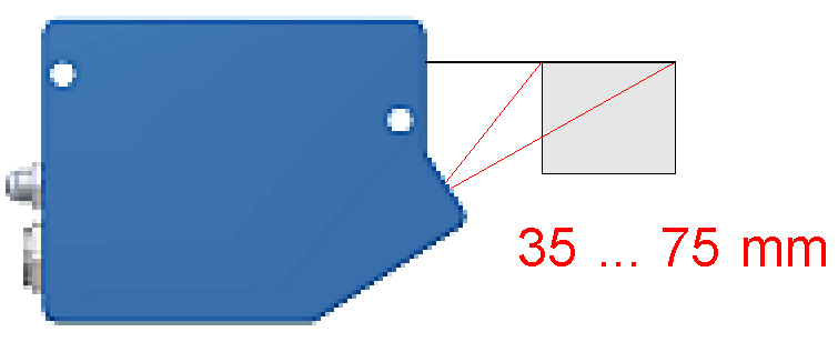 |
| L-LAS-LT-120-CL | 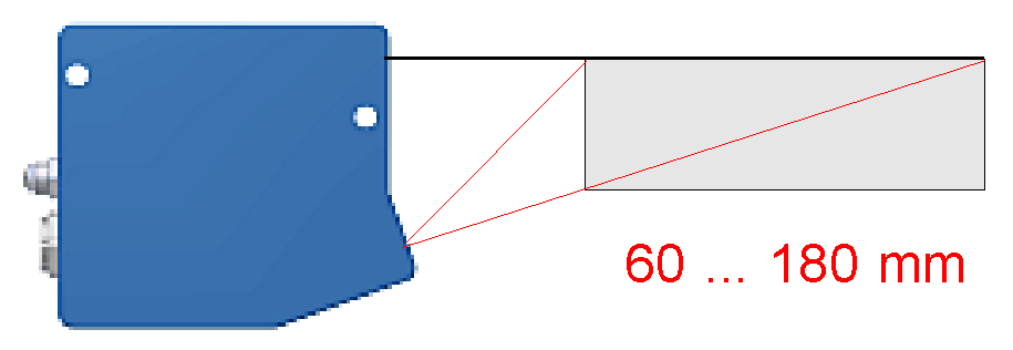 |
| L-LAS-LT-165-CL | 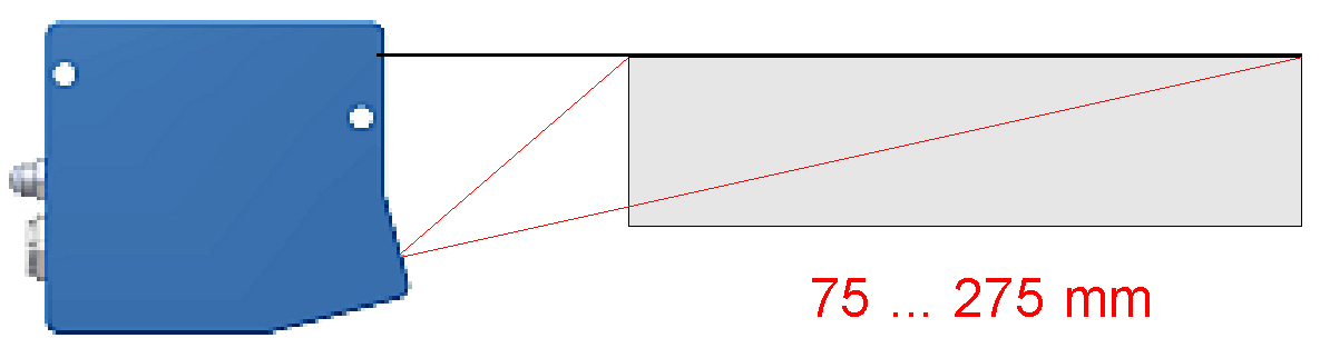 |
| L-LAS-LT-250-CL | 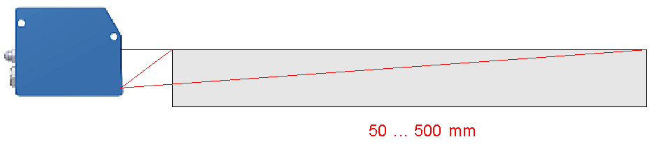 |
| L-LAS-LT-85-RA-CL (special version) |
 |
| L-LAS-LT-157-CL (special version) |
 |
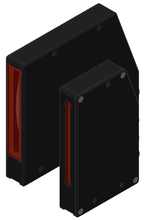
MASTER/SLAVE types
L-LAS-LT-55-MA and L-LAS-LT-55-SL
(L-LAS-LT-55-HS-MA and L-LAS-LT-55-HS-SL)
L-LAS-LT-37-MA and L-LAS-LT-37-SL
(L-LAS-LT-37-HS-MA and L-LAS-LT-37-HS-SL)
L-LAS-LT-80-MA and L-LAS-LT-80-SL
(L-LAS-LT-80-HS-MA and L-LAS-LT-80-HS-SL)
L-LAS-LT-110-MA and L-LAS-LT-110-SL
(L-LAS-LT-110-HS-MA and L-LAS-LT-110-HS-SL)
L-LAS-LT-135-MA and L-LAS-LT-135-SL
(L-LAS-LT-135-HS-MA and L-LAS-LT-135HS-SL)

LAS-LT-160-MA and L-LAS-LT-160-SL
(L-LAS-LT-160-HS-MA and L-LAS-LT-160-HS-SL)
LAS-LT-200-MA and L-LAS-LT-200-SL
(L-LAS-LT-200-HS-MA and L-LAS-LT-200-HS-SL)
.jpg)
L-LAS-LT-275-MA and L-LAS-LT-275-SL
(L-LAS-LT-275-HS-MA and L-LAS-LT-275-HS-SL)
L-LAS-LT-450-MA and L-LAS-LT-450-SL
(L-LAS-LT-450-HS-MA and L-LAS-LT-450-HS-SL)
L-LAS-LT-1000-MA and L-LAS-LT-1000-SL
(L-LAS-LT-1000-HS-MA and L-LAS-LT-1000-HS-SL)
L-LAS-LT-1500-MA and L-LAS-LT-1500-SL
(L-LAS-LT-450-HS-MA and L-LAS-LT-450-HS-SL)

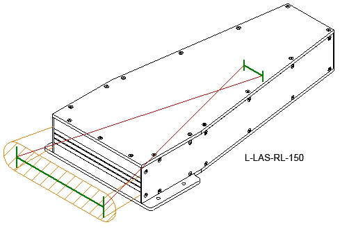
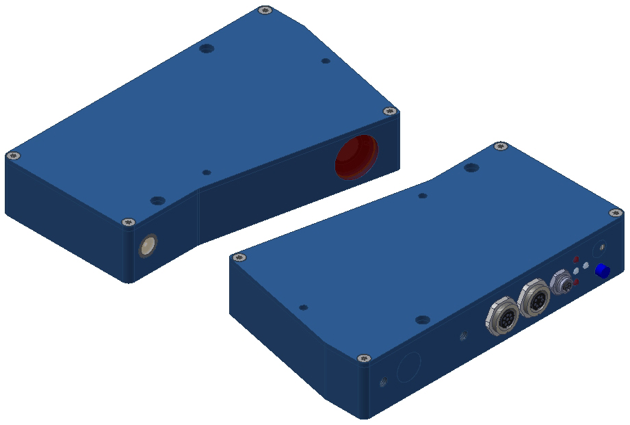
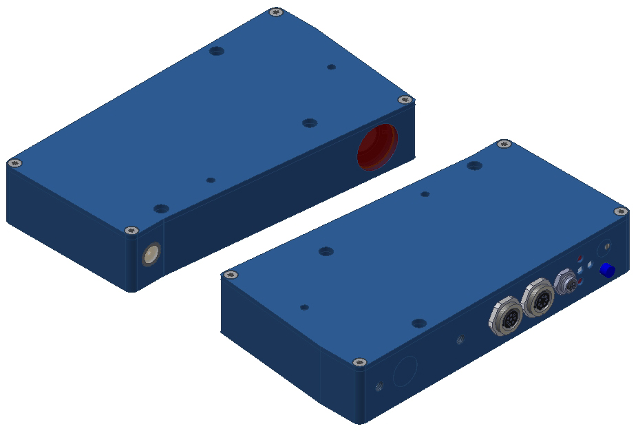
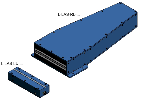
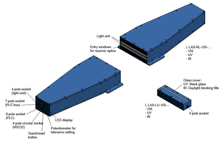
The sensor systems of the L-LAS-RL series are equipped with a line camera with precision lens and with an LED light unit that is available with UV light, white-light, and IR light. Corresponding filters are available for the camera lens. All the components are contained in a highly robust aluminium housing, optics and light unit are protected by a scratch-proof glass cover. As an option the L-LAS-RL series also can be operated with external light units of the L-LAS-LU series, which also are available as UV, white-light, and IR types. The measuring ranges of the individual L-LAS-RL types lie between 15 mm and 500 mm.
L-LAS-RL overview
| L-LAS-RL-15 (white-light) |  |
| L-LAS-RL-CON1 |  |
| L-LAS-RL-10-W (-R, -B, -UV, -IR) L-LAS-RL-20-W (-R, -B, -UV, -IR) L-LAS-RL-30-W (-R, -B, -UV, -IR) L-LAS-RL-40-W (-R, -B, -UV, -IR) |
 |
| L-LAS-RL-10-W (-R, -B, -UV, -IR)-CL L-LAS-RL-20-W (-R, -B, -UV, -IR)-CL L-LAS-RL-30-W (-R, -B, -UV, -IR)-CL L-LAS-RL-40-W (-R, -B, -UV, -IR)-CL |
 |
 |
||
External light unit: |
||
|
L-LAS-RL-50-VIS-… (white-light)
L-LAS-RL-50-UV-… (UV light) L-LAS-RL-50-IR-… (IR light) L-LAS-RL-100-VIS-…(white-light) L-LAS-RL-100-UV-…(UV light) L-LAS-RL-100-IR… (IR light) L-LAS-RL-150-VIS-… (white-light) L-LAS-RL-150-UV… (UV light) L-LAS-RL-150-IR-… (IR light) L-LAS-RL-300-VIS-… (white-light)
L-LAS-RL-300-UV-… (UV light)
L-LAS-RL-300-IR-… (IR light)
L-LAS-RL-500-VIS-… (white-light)
L-LAS-RL-500-UV-… (UV light)
L-LAS-RL-500-IR-… (IR light)
|
L-LAS-LU-50-VIS (white-light)
L-LAS-LU-50-UV (UV light) L-LAS-LU-50-IR (IR light) L-LAS-LU-100-VIS (white-light)
L-LAS-LU-100-UV (UV light)
L-LAS-LU-100-IR (IR light)
L-LAS-LU-150-VIS (white-light)
L-LAS-LU-150-UV (UV light)
L-LAS-LU-150-IR (IR light)
L-LAS-LU-300-VIS (white-light)
L-LAS-LU-300-UV (UV light)
L-LAS-LU-300-IR (IR light)
L-LAS-LU-500-VIS (white-light)
L-LAS-LU-500-UV (UV light)
L-LAS-LU-500-IR (IR light)
|
|
L-LAS-RL-15-FE
L-LAS-RL-50-…- (HS)
-VIS: with white-light LEDs
-UV: with UV LEDs, black glass and UV blocking filter
-IR: with IR filter (daylight blocking filter)
-UV: with UV LEDs, black glass and UV blocking filter
-IR: with IR filter (daylight blocking filter)
-UV: with UV LEDs, black glass and UV blocking filter
-IR: with IR filter (daylight blocking filter)
-UV: with UV LEDs, black glass and UV blocking filter
-IR: with IR filter (daylight blocking filter)
-UV: with UV LEDs, black glass and UV blocking filter
-IR: with IR filter (daylight blocking filter)
-UV: with UV LEDs, black glass and UV blocking filter
-IR: with IR filter (daylight blocking filter)