


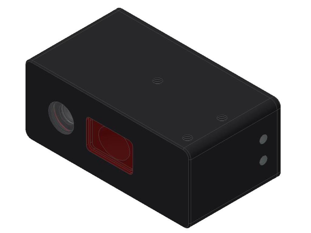
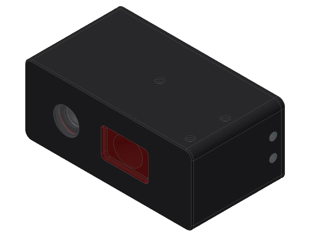
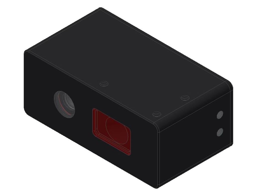
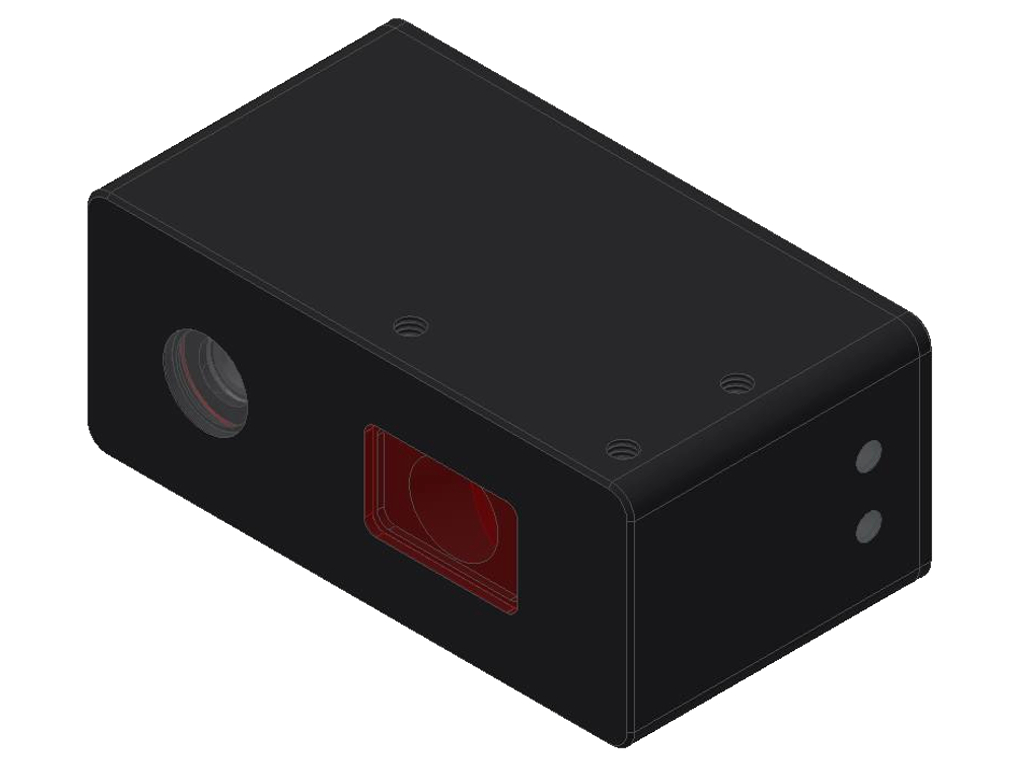
L-LAS-LT-ML Series
Laser distance line sensors (Mini Line)| Type | Light source | Meas. range (begin...end) | Resolution/ Reprodu- cibility | Line- arity | Laser line geometry | Max. scan frequency | LxWxH (mm) | Data sheet |
CAD data |
Appl. | ||
|---|---|---|---|---|---|---|---|---|---|---|---|---|
| L-LAS-LT-30-ML | Line laser, 670nm, <0.39mW (CL. 1) | typ. 24mm (21mm...45mm) | 6µm / ±6µm | 0.25% FSR (full scale range) | Ø0.3mm | 2kHz (NORMAL) 3.3kHz (FAST) | 72x30x40 |
|
|
|||
| L-LAS-LT-50-ML | Line laser, 670nm, <0.39mW (CL. 1) | typ. 38mm (32mm...70mm) | 10µm / ±10µm | 0.25% FSR (full scale range) | Ø0.3mm | 2kHz (NORMAL) 3.3kHz (FAST) | 72x30x40 |
|
|
|||
| L-LAS-LT-80-ML | Line laser, 670nm, <0.39mW (CL. 1) | typ. 100mm (40mm...140mm) | 20µm / ±20µm | 0.25% FSR (full scale range) | Ø0.3mm | 2kHz (NORMAL) 3.3kHz (FAST) | 72x30x40 |
|
|
|||
| L-LAS-LT-130-ML | Line laser, 670nm, <0.39mW (CL. 1) | typ. 150mm (50mm...200mm) | 40µm / ±40µm | 0.25% FSR (full scale range) | Ø0.3mm | 2kHz (NORMAL) 3.3kHz (FAST) | 72x30x40 |
|
|
GENERAL TECHNICAL DATA:
| Software | Windows® PC software: L-LAS-LT-Scope |
| Voltage supply | +24VDC (± 10%), reversed polarity protected, overload protected |
| Current consumption | <200mA |
| Max. switching current | 100mA, short-circuit proof |
| Light source | Semi-conductor laser, 670 nm, <0.39mW opt. power, DC-operation, laser class 1 acc. to DIN EN 60825-1:2015-07 (IEC 60825-1:2014) |
| Line detector | CCD line detector with 512 pixels, 2048 subpixels |
| Reference distance | L-LAS-LT-80-ML: 80mm |
| Measuring range | depends on sensor type |
| Resolution/reproducibility | depends on sensor type |
| Linearity | depends on sensor type |
| Laser line geometry | Visible red laser spot (typ. Ø 0.3mm) |
| Optical filter | Interference filter, red light filter |
| Analog outputs (2x) | ANA: Voltage 0...+10V I-OUT: Current 4...20mA |
| Digital output (1x) | OUT0: pnp bright-switching/npn darks-switching or pnp dark-switching/npn bright-switching Output polarity can be adjusted under Windows® on PC |
| Digital inputs (2x) | IN0: External trigger IN1: Teach/Reset (double function) Input voltage +Ub/0V, with protective circuit |
| Sensititivy | adjustable under Windows® on PC |
| Laser power correction | adjustable under Windows® on PC |
| Temperature stability | 0.01% of measuring range/°C |
| LED display | 1x three-color LED red/green/blue for tolerance band monitoring: red = Measuring value outside the tolerance window green = Measuring value within tolerance window blue = Measuring value outside the measuring range 1x three-color LED red/green/blue for power indication: green = Power |
| Scan frequency | max. 2kHz (at video speed = NORMAL) or max. 3.3kHz (at video speed = FAST) |
| Interface | RS232, parameterizable under Windows® |
| Housing dimensions | depends on sensor type |
| Housing material | Aluminum, anodized in black |
| Type of connector | - to PLC: 8-pole fem. M8 connector Binder 718/768 - to PC: 4-pole fem. connector Binder 707 |
| Connecting cables | - to PLC: cab-las8/SPS-M8-...-shd - to PC: cab-las4/PC, cab-4/USB or cab-4/ETH |
| Operating temp. range | -10°C ... +50°C |
| Storage temp. range | -20°C ... +85°C |
| Enclosure rating | IP67 |
| EMC test acc. to | DIN EN 60947-5-2 |