


Translate this page:
What is gloss?
Calibration surfaces
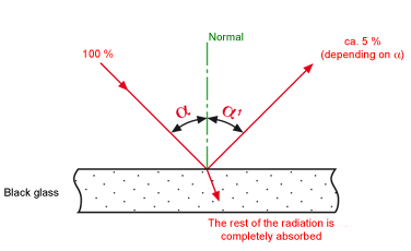
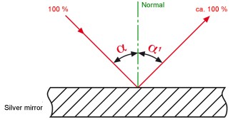
When a silver mirror is used, this surface is used as a reference and is defined as 100 (unit: [1]).
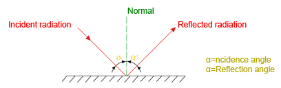
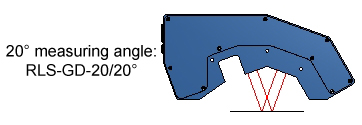
Measuring angle
For high-gloss surfaces.
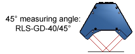
TAPPI standard (paper industry) for glossy surfaces.
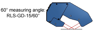
For semi-gloss surfaces.
A 60° gloss sensor is used if gloss grades >10GU to <70GU are to be determined. This variant is an "all-rounder". The 60° gloss sensor is therefore standard for most applications.
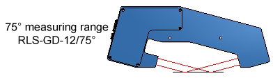
TAPPI standard (paper industry) for matt surfaces.
For matt surfaces.
|
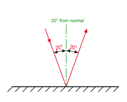
20° from normal
Depending on the application the gloss sensor is calibrated to black glass or to a silver mirror (special sensor version).This measuring geometry primarily is used for high-gloss objects such as high-gloss aluminium, high-gloss plastic films, or coated glass plates. |
 |
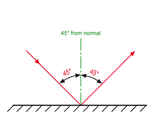 |
45° from normal
Calibration is performed to black glass. The gloss level of black glass is 100 [1].
The gloss level of black glass is 100 [1]. In the special versions calibrated to silver mirrors it also is 100 [1]. This measuring geometry almost exclusively is used in the paper industry for measuring high-gloss paper surfaces (so-called TAPPI standard). |
|
60° from normal |
 |
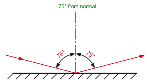 |
75° from normal
This measuring angle preferably is used in the paper industry for the measurement of dull paper surfaces (TAPPI standard). Calibration is performed to black glass, the gloss level is 100 [1]. |
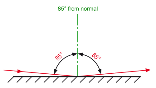
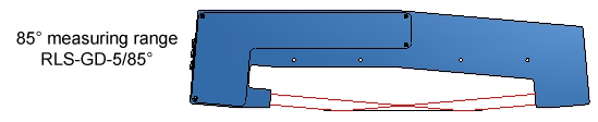
| 85° from normal This measuring geometry primarily is used for the measurement of very dull surfaces (e.g. dull wood surfaces). Calibration here also is performed to black glass with a gloss level of 100 [1]. |
 |
Hand-held devices
The market offers a wide variety of OFFLINE devices (hand-held devices) that can be used to measure the gloss level for example in a laboratory. With sheet material a sample usually is taken at production start for measurement in the laboratory. Another sample then is taken at the end of production. This of course means that no proper gloss measurement can be performed between the start and end of production. In the production of plate material, however, samples also can be taken during production. This method, however, takes a lot of time, and as a rule the samples that were taken can hardly be fed back into the production sequence.
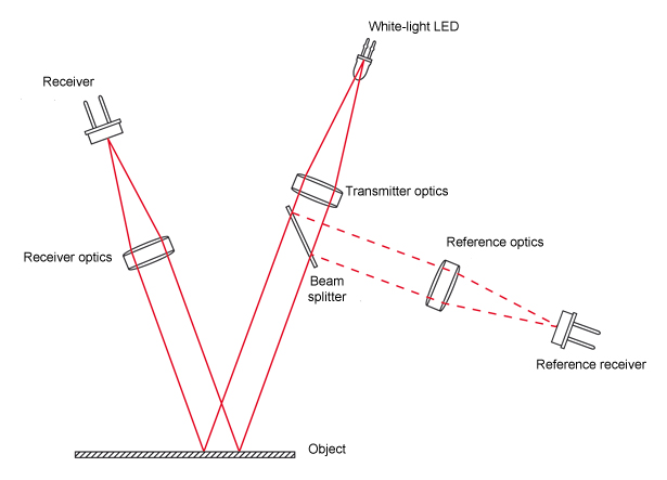
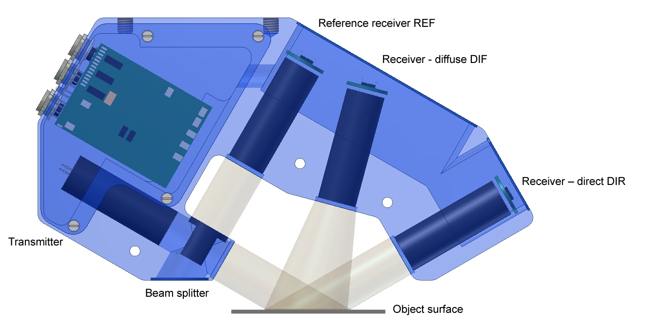
As a rule a bulb is used as a light source. Transmitter optics provide the parallel alignment of the white light (as a rule the light beam has a diameter of less than 10mm). A beam splitter couples out a part of the transmitter light, which through an optical unit (reference optics) is directed onto the reference receiver, which allows the compensation of possible drifts.

- ONLY OFFLINE measurements are possible, which means it is necessary to take samples. Sheet material only can be measured at the start and end of the sheet!
- Measurements are only possible on a random basis (in a laboratory). 100% product measurement is not possible!
- Non-contacting measurement is impossible because the sensor must rest on the object to be measured!
- Sensitivity to extraneous light, because as a rule a bulb is used as a light source (not modulated).
- Limited service life of the light source (bulb).
- No digital switching outputs, no analog outputs.
INLINE measuring devices (of Sensor Instruments GmbH)
The design of INLINE devices basically is similar to that of hand-held devices, but there are some essential differences:
- A white-light LED is used instead of a bulb, which means that the light can be modulated, and the measurement system is insensitive to extraneous light.
- Due to its insensitivity to extraneous light the measurement system operates in a non-contacting manner and can thus be used INLINE.
- The reference branch can be placed outside. Environmental influences thus equally apply to the measuring distance and to the reference distance.
- The optics cover consists of plane glass, which considerably facilitates cleaning of the optics.
- The system features switching outputs and 2 analog outputs (voltage and current output).
- Several serial interfaces (by way of converters) are available: RS232, USB and Ethernet.
- With a monitor unit several measuring lines can be represented by means of a multiplexer unit (trend display, numerical and graphic display of the gloss level, display of the average, the set tolerance value, and recording of data for a certain job number).
- Since the transmitter power of the white-light LED can be varied, the light power can be optimally adapted to the current surface to be measured.
- The special light beam has a diameter of approx. 20mm, which means that a much bigger section of the object surface is scanned than with hand-held devices. The measurement system thus becomes insensitive to local variations
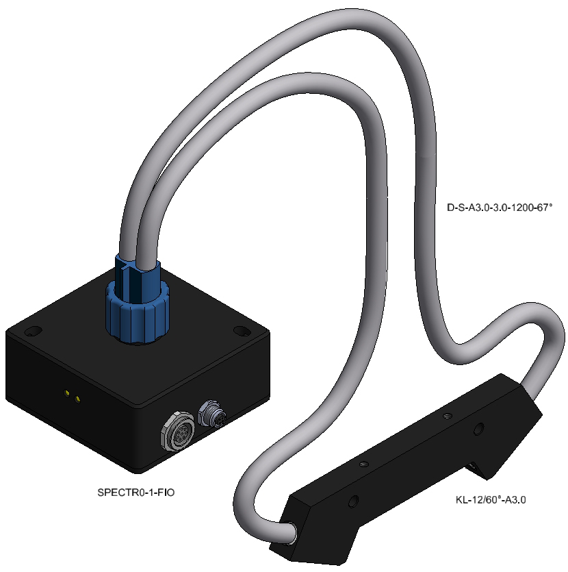
The gloss sensor essentially comprises a light source (SI: modulated white-light LED) in the transmitter optics, a beam splitter that couples out a part of the transmitter radiation and provides it to the reference receiver, the receiver optics, and the actual receiver.
Measuring geometry
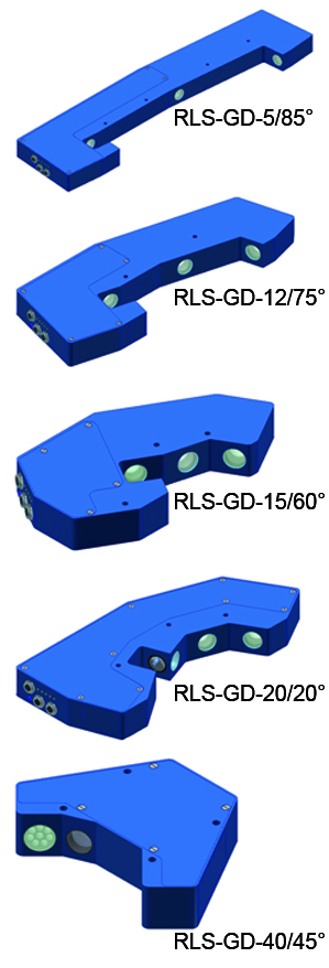
Sensor Instruments provides INLINE gloss sensors for all the important standards:
Interfacing
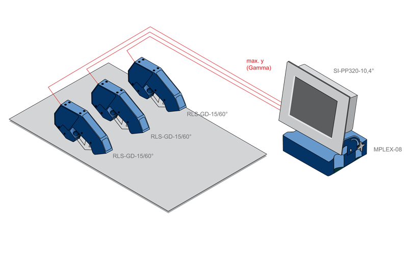
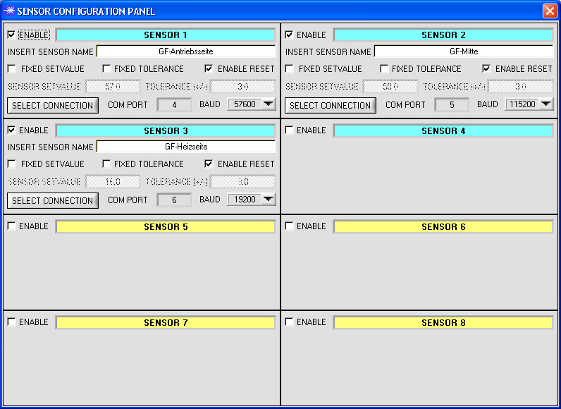
The gloss sensor features 5 digital outputs that can be correspondingly evaluated by a downstream PLC. Up to 31 gloss levels (with corresponding tolerances) can be represented (binary-coded). The sensor also has two analog outputs that provide information about the current gloss level: A voltage output (0 V…10 V) and a current output (4 mA ... 20 mA). The integrated RS232 interface can be used for data transmission. External interface converters for USB and Ethernet can be used for connection to the respective systems. The M-PLEX-08 multiplexer unit allows the linking of up to 8 gloss measurements (RLS-GD sensors), the measurement values of which furthermore can be displayed graphically (trend display) and numerically (current or average value) with a monitoring unit (SI-PP320-10.4°). It also is possible to record data and save them related to the respective job.
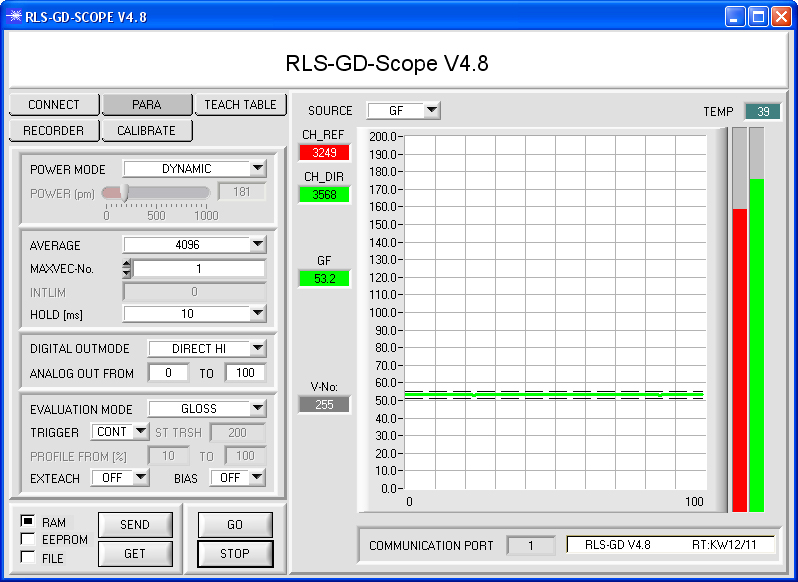
Software
The gloss sensor can be comfortably and easily parameterised with the RLS-GD-Scope V4.8 Windows® software. The software also displays the most important parameters such as the raw value of the reference receiver and of the receiver for direct reflection.
Important input parameters:
-
Light power of the white-light LED automatically corrected / not automatically corrected:
POWER MODE: DYNAMIC/STATIC
Setting of the light power for STATIC operation:
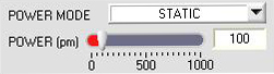
0: LED off
1000: LED at maximum
-
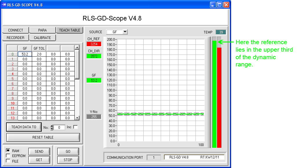
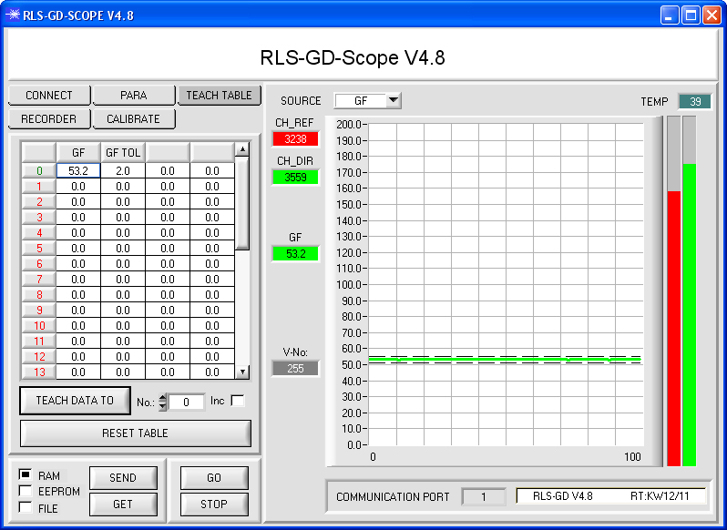
Averaging of the determined gloss values:
In POWER MODE DYNAMIC the controller that is integrated in the gloss sensor tries to control the light power in such a way that either the raw value of the reference signal or the raw value of the receiver for direct reflection lies in the upper third of the dynamic range (see the bar display on the user interface).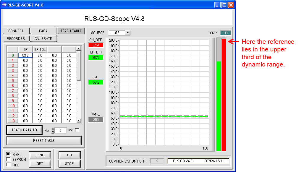
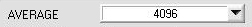
-
The average can be set between 1 and 32000:
-
Setting of the number of gloss levels that should be provided at the digital outputs MAX-W6:
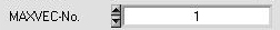
-
Up to 5 gloss levels can be output directly. For more than 5 gloss levels the output can be binary-coded.
-
Evaluation mode NORM or GLOSS:
In evaluation mode GLOSS a continuous comparison is made with the reference signal, which always represents the value of calibration to black glass (or silver mirror). The relation MEASURING CHANNEL / REFERENCE during calibration serves as a reference point here. Only the GLOSS mode is used for gloss measurement. The NORM mode is explained in more detail in the GLOSS INSPECTION chapter. -
Analog output:
The analog value usually represents a gloss level from 0 to 100 (0V…+10V). However, this range can be zoomed with a factor of 10, so that e.g. a gloss level range of 5 to 15 can then be output as an analog value of 0V to 10V (or 4 mA to 20 mA). -
Gloss level table
.jpg)
-
Graphical and numerical display: The gloss level, the reference value, and the measurement value are displayed in numerical form. The gloss level furthermore is displayed in graphical form. Up to 31 different gloss levels can be saved in the teach table. The tolerances also can be set. It also is possible to enter the same gloss level GN and set a tolerance GTO that increases in the table from top to bottom. The gloss sensor then processes the table from top to bottom. The value that is true first (lies within the tolerance) is sent to the digital outputs in the form of the table number. With the help of the teach table the gloss level thus can be divided into classes (e.g. acc. to increasing tolerance or in cascaded form).
-
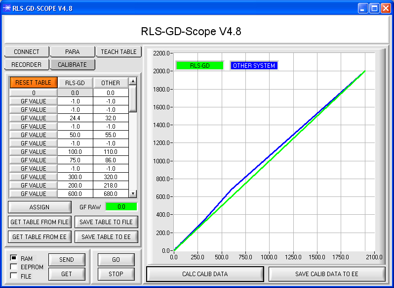
Calibration
A click on the button opens the CALIBRATE window:
-
A selection can be made here between calibration to a target (as a rule black glass, or with the RLS-GD-20/20°-UV a silver mirror), or adaptation to a hand-held device. Possible deviations between INLINE devices and hand-held measurement devices can thus be compensated, and the operator then has two devices that display the same value. Such deviations often are caused by dirty calibration dishes (black glass) of the hand-held devices, or by aged devices.

-
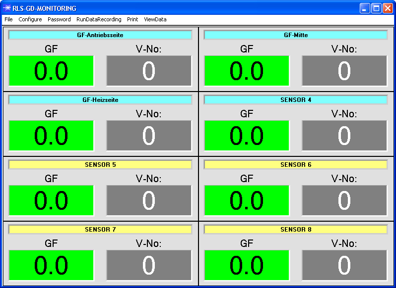
With the RLS-GD-MONITORING V4.8 monitoring software the gloss levels of up to 8 sensors can be simultaneously displayed in combination with the MPLEX-08 multiplexer unit and the SI-PP320-10.4" monitor unit. The gloss levels can be displayed both in numerical and in graphical form as a trend display. The recorded values furthermore can be assigned to a certain job number.
RLS-GD series
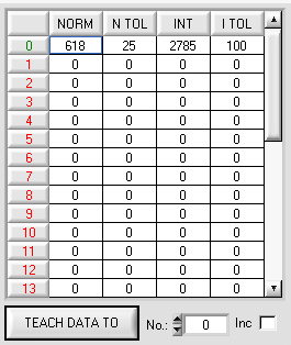
Gloss sensors of the RLS-GD series also are excellently suited for gloss inspection. For such applications the evaluation mode NORM is selected in the RLS-GD-Scope V4.8 parameterisation software.
![]()
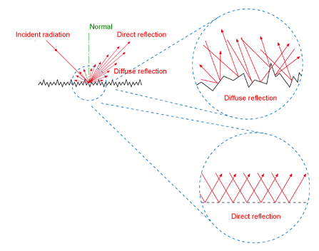
In this mode direct reflection is put into relation to diffuse reflection. It is also possible here to save up to 31 gloss values in the TEACH table.
Both the NORM value and the NORM tolerance value can be changed manually. The table is processed from top to bottom. The first value in the table that matches the currently processed NORM value is output at the digital outputs either directly or binary-coded (depending on the parameterisation and on the number of taught values).
Available gloss sensor types:
In addition to the digital outputs the sensors also have two analog outputs that provide information about the NORM value: 1x voltage output (0V…+10V), 1x current output (4 mA … 20 mA).

The RLS-GD-Scope V… software also is used as a user interface in gloss inspection for parameterisation of the gloss sensor and for monitoring the raw data of the determined values.
Setting parameters such as transmitter power automatically controlled / not automatically controlled (DYN/STAT), transmitter power (in STAT mode), averaging (AVERAGE), number of teach values, output mode (direct or binary-coded, pulse lengthening), evaluation mode, tolerance in the teach table can be easily and comfortably entered under Windows®.
The SPECTRO1-Scope V2.0 Windows® software can be used to for example set the tolerance band around the current gloss level, the light power, averaging, and gain. It also is possible to activate an EXTERNTEACH function, which allows easy teaching by way of the PLC program control.
Gloss inspection already solves quite a number of applications. However, there still are problems where color also must be inspected in addition to the gloss level.
SI-COLO-GD-40 is an inspection system that measures both the gloss level and the color value. This makes it possible to detect even smallest differences between individual products.
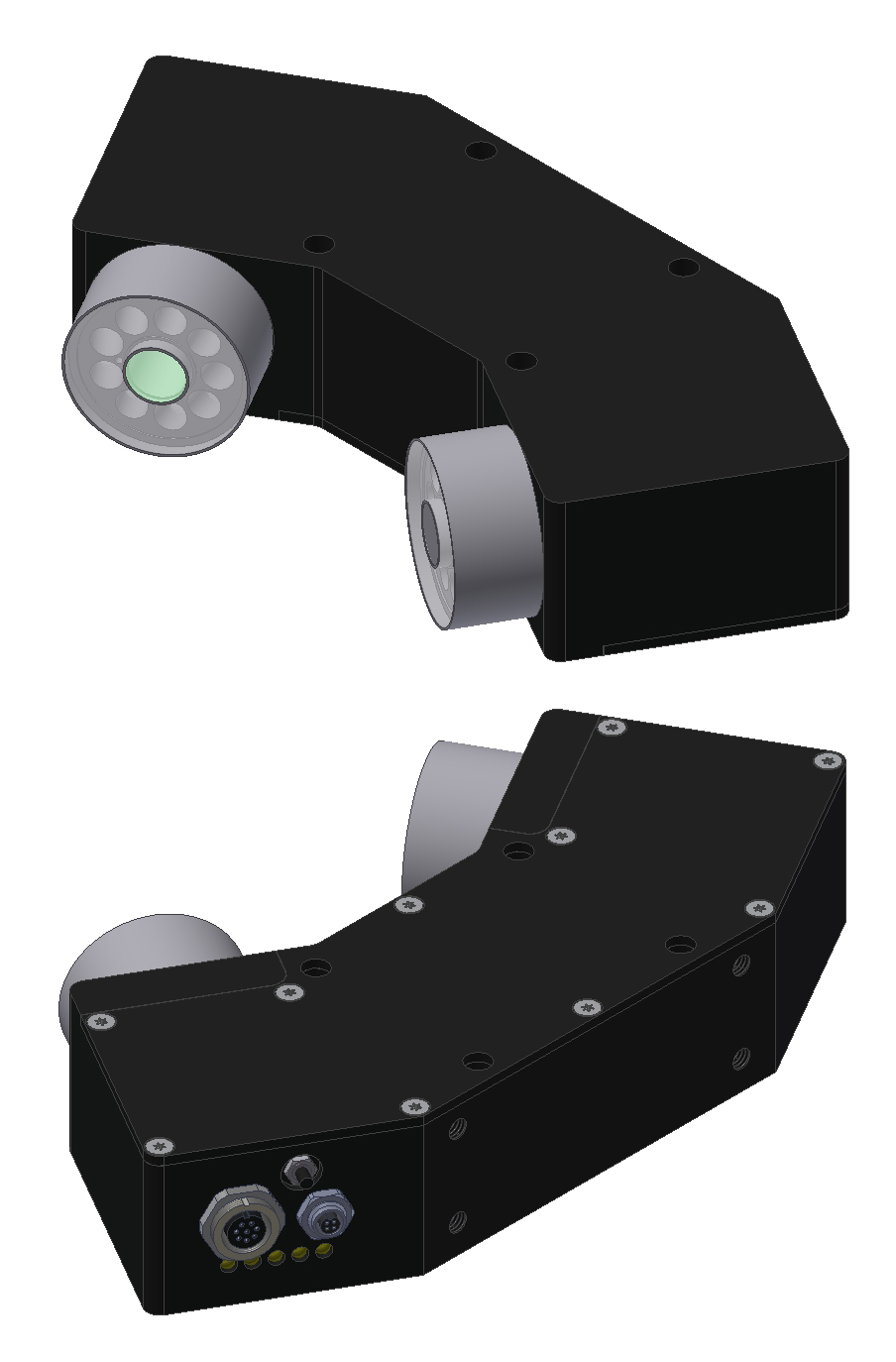
Color-gloss sensor SI-COLO-GD-40
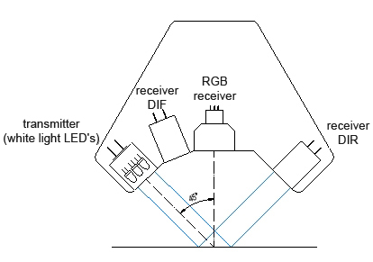
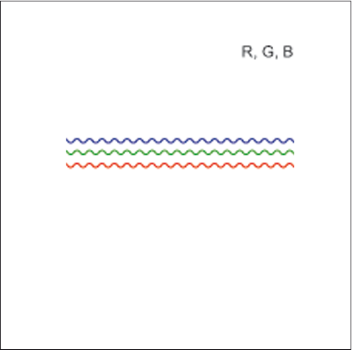
The SI-COLO-GD-40 color-gloss sensor essentially is a combination of a color sensor from the SI-COLO4 series with components of a gloss sensor from the RLS-GD series. The sensor's light source comprises white-light LEDs with modulated light to achieve a better insensitivity to extraneous light. Apart from the color detector (R, G, B raw values), a detector for the directly reflected component (DIR) and a detector for the diffusely reflected component (DIF) also provide information to the controller that is integrated in the color-gloss sensor.

Color evaluation is performed according to the following algorithms:
![]()
As an alternative the so-called s, i, M values also are available for the color sensors.
Gloss evaluation is performed with the following formula: ![]()
In addition to the raw data (R, G, B, DIR, DIF) the controller thus also can operate with the parameters x, y, INT, GN and s, i, M, GN.
Whereas x, y, INT and s, i, M provide information about the color value, the GN value provides information about the gloss behaviour of the object.
Essentially the following modes are available for evaluation:
x, y, INT GN
s, i, M GN
x, y, INT, GN
s, i, M, GN
Teaching is performed as with the color sensors, only an additional parameter has been added: GN!
With x, y, INT and GN the table therefore looks as follows:
|
Nb |
x |
y |
INT |
CTO |
GN |
GTO |
|
0 |
|
|
|
|
|
|
|
1 |
|
|
|
|
|
|
|
2 |
|
|
|
|
|
|
|
3 |
|
|
|
|
|
|
x, y, INT GN
|
Nb |
x |
y |
INT |
CTO |
GN |
GTO |
|
0 |
|
|
|
|
|
|
|
1 |
|
|
|
|
|
|
|
2 |
|
|
|
|
|
|
x, y, INT GN
And with s, i, M and GN the table looks as follows:
|
Nb |
x |
y |
INT |
CTO |
GN |
GTO |
|
0 |
|
|
|
|
|
|
|
1 |
|
|
|
|
|
|
|
2 |
|
|
|
|
|
|
|
3 |
|
|
|
|
|
|
s, i, M GN
|
Nb |
s |
i |
M |
GN |
CGTO |
|
0 |
|
|
|
|
|
|
1 |
|
|
|
|
|
|
2 |
|
|
|
|
|
|
3 |
|
|
|
|
|
s, i, M GN
Evaluation also depends on the set selection mode:
BEST HIT
FIRST HIT
MINIMAL DISTANCE
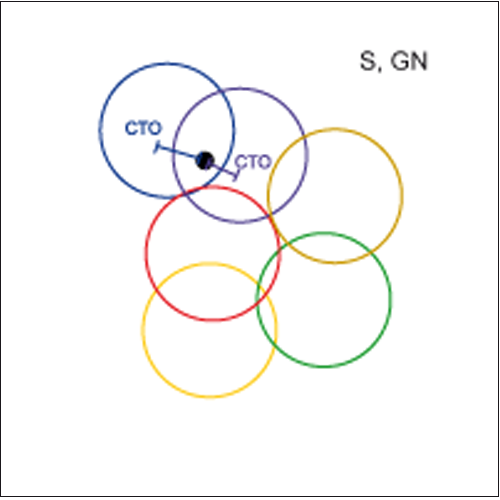
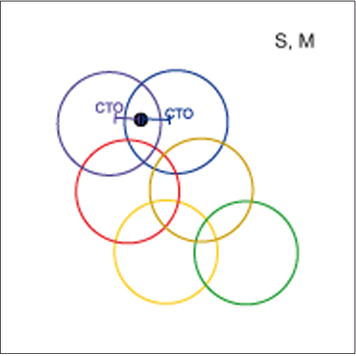
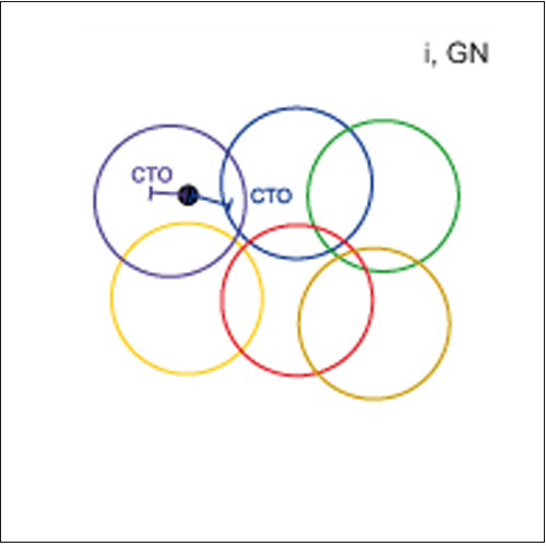
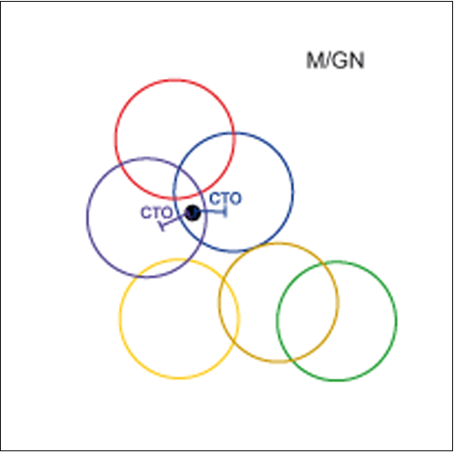
In evaluation mode x, y, INT GN and s, i, M GN the sensor first checks whether the current color-gloss value lies within the specified tolerance window of GN, i.e. GTO. Then it checks whether the condition for the color value (within CTO) is true. If several candidates are eligible, the selection is made according to the set selection mode (BEST HIT, FIRST HIT, MINIMAL DISTANCE, see COLOR INSPECTION).
In evaluaton mode x, y, INT, GN and s, i, M, GN, on the other hand, the sensor performs color/gloss selection in a "four-dimensional space", the tolerance CGTO creates a four-dimensional structure. The current color-gloss value must lie within the tolerance range if the taught color-gloss value should be eligible as a possible candidate.
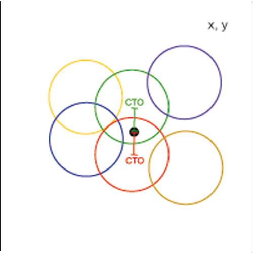
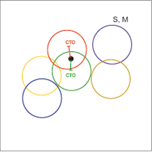
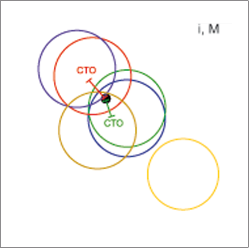
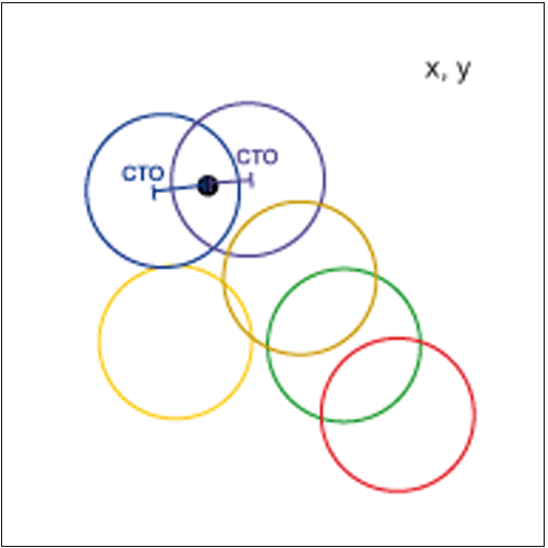
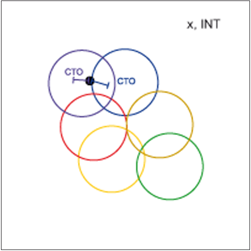
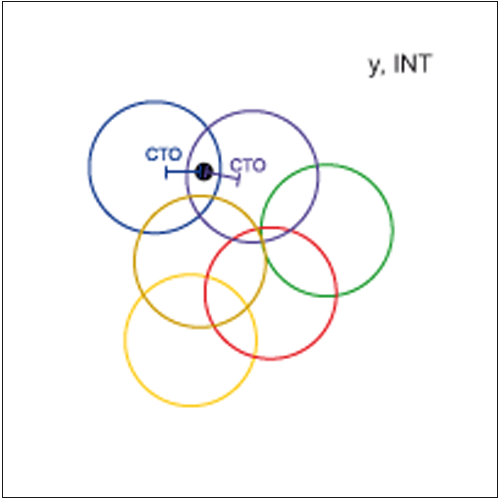
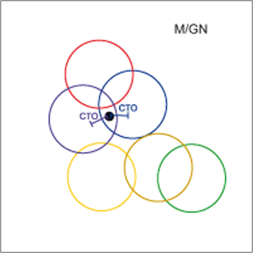
GRAPHIC REPRESENTATION in x, y, INT GN and s, i, M GN EVALUATION MODE:
The x, y, INT and s, i, M values are shown in 3 views. The GN value is represented as a bar display.
Saved color-gloss values:
.png)


![]()

![]()
In BEST HIT selection mode: Color-gloss value 5
In MINIMAL-DISTANCE selection mode: Color-gloss value 5
In FIRST HIT selection mode: Color-gloss value 1
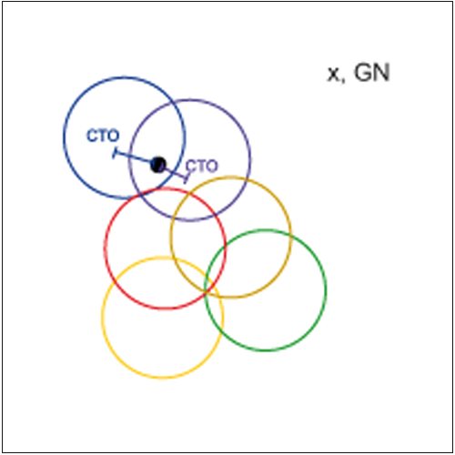
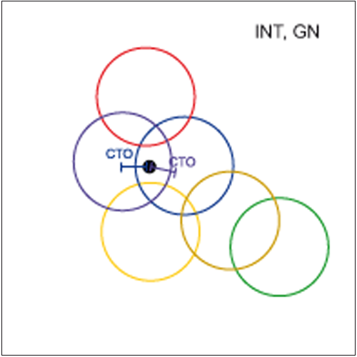
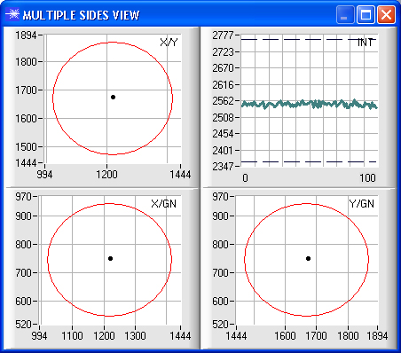
GRAPHIC REPRESENTATION in x, y, INT, GN and s, i, M, GN EVALUATION MODE:
In these two modes the x, y, INT, GN and s, i, M, GN value is represented in 6 views:
Saved color-gloss values:

Saved color-gloss values:
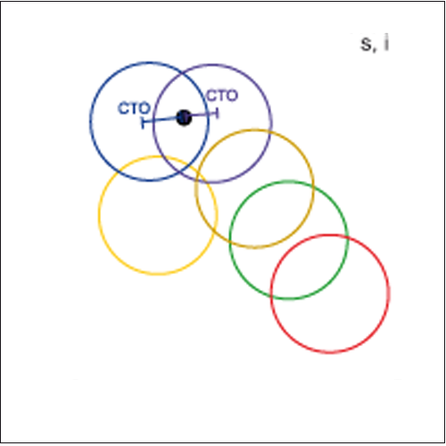
In BEST HIT selection mode: Color-gloss value 3
In MINIMAL DISTANCE selection mode: Color-gloss value 3
In FIRST HIT selection mode: Color-gloss value Ø
Windows ® user interface SI-COLO-GD-SCOPE: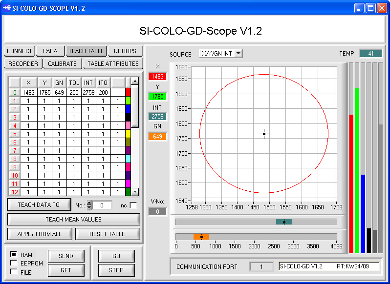
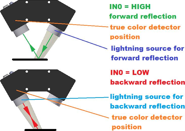
Color-gloss inspection with the SPECTRO-3-50-FCL-30°/30°
|
The color-gloss sensor type SPECTRO-3-50-FCL-30°/30° comes with two lightning sources which will be used alternately dependent of the IN0-signal level. The sensor is used for objects with very small color as well as gloss differences, e.g. leather imitations, leather and plastic components for the automotive interior field but also for differentiation of plastic films and plastic laminations for the furniture industry. |
|
|
|
|
|
|
|
|

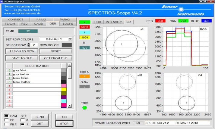
Windows ® user interface SPECTRO-3-SCOPE:

